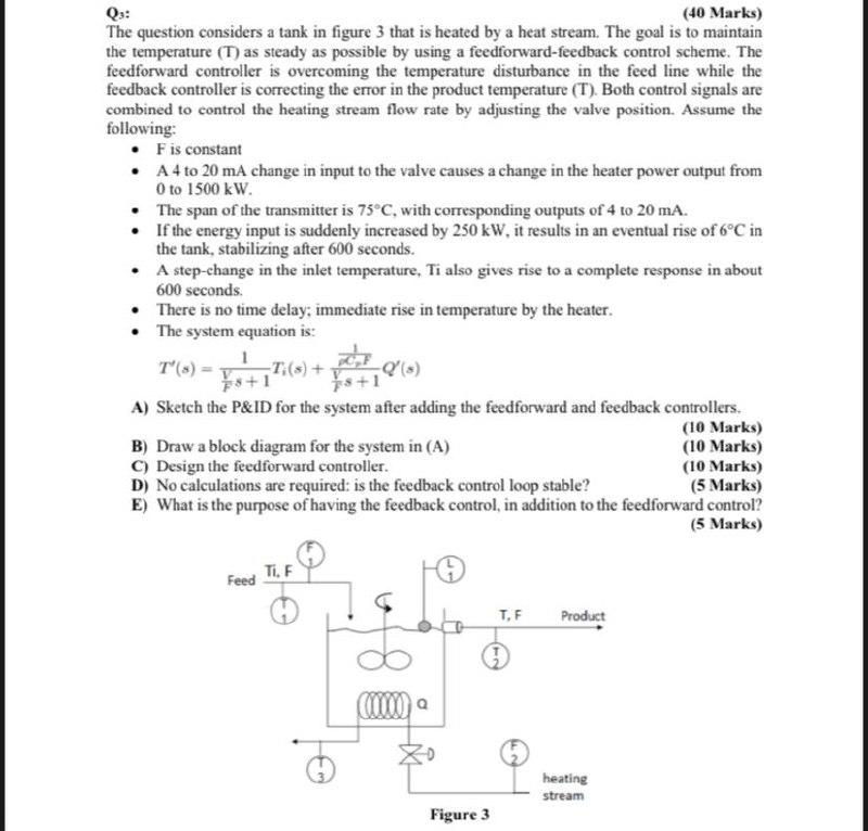
(40 Marks) The question considers a tank in figure 3 that is heated by a heat stream. The goal is to maintain the temperature (T) as steady as possible by using a feedforward-feedback control scheme. The feedforward controller is overcoming the temperature disturbance in the feed line while the feedback controller is correcting the error in the product temperature (T). Both control signals are combined to control the heating stream flow rate by adjusting the valve position. Assume the following: F is constant A 4 to 20 mA change in input to the valve causes a change in the heater power output from 0 to 1500 kW. The span of the transmitter is 75C, with corresponding outputs of 4 to 20 mA. If the energy input is suddenly increased by 250 kW, it results in an eventual rise of 6C in the tank, stabilizing after 600 seconds. A step-change in the inlet temperature, Ti also gives rise to a complete response in about 600 seconds There is no time delay; immediate rise in temperature by the heater. The system equation is: T'(x) = :*) 2 T(s) + 8+1 A) Sketch the P&ID for the system after adding the feedforward and feedback controllers. (10 Marks) B) Draw a block diagram for the system in (A) (10 Marks) C) Design the feedforward controller. (10 Marks) D) No calculations are required: is the feedback control loop stable? (5 Marks) E) What is the purpose of having the feedback control, in addition to the feedforward control? (5 Marks) 18+1 Feed Ti, F TF Product heating stream Figure 3 (40 Marks) The question considers a tank in figure 3 that is heated by a heat stream. The goal is to maintain the temperature (T) as steady as possible by using a feedforward-feedback control scheme. The feedforward controller is overcoming the temperature disturbance in the feed line while the feedback controller is correcting the error in the product temperature (T). Both control signals are combined to control the heating stream flow rate by adjusting the valve position. Assume the following: F is constant A 4 to 20 mA change in input to the valve causes a change in the heater power output from 0 to 1500 kW. The span of the transmitter is 75C, with corresponding outputs of 4 to 20 mA. If the energy input is suddenly increased by 250 kW, it results in an eventual rise of 6C in the tank, stabilizing after 600 seconds. A step-change in the inlet temperature, Ti also gives rise to a complete response in about 600 seconds There is no time delay; immediate rise in temperature by the heater. The system equation is: T'(x) = :*) 2 T(s) + 8+1 A) Sketch the P&ID for the system after adding the feedforward and feedback controllers. (10 Marks) B) Draw a block diagram for the system in (A) (10 Marks) C) Design the feedforward controller. (10 Marks) D) No calculations are required: is the feedback control loop stable? (5 Marks) E) What is the purpose of having the feedback control, in addition to the feedforward control? (5 Marks) 18+1 Feed Ti, F TF Product heating stream Figure 3