Answered step by step
Verified Expert Solution
Link Copied!

Question

1 Approved Answer

4.13* The adder-subtractor circuit of Fig. 4.13 has the following values for mode input M and data inputs A and B. In each case, determine
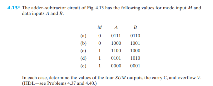
image text in transcribed

4.13* The adder-subtractor circuit of Fig. 4.13 has the following values for mode input M and data inputs A and B. In each case, determine the values of the four SUM outputs, the carry C, and overflow V. (HDL-see Problems 4.37 and 4.40.)

Step by Step Solution

There are 3 Steps involved in it

Step: 1

blur-text-image

Get Instant Access to Expert-Tailored Solutions

See step-by-step solutions with expert insights and AI powered tools for academic success

Step: 2

blur-text-image

Step: 3

blur-text-image

Ace Your Homework with AI

Get the answers you need in no time with our AI-driven, step-by-step assistance

Get Started

Recommended Textbook for

Privacy In Statistical Databases International Conference Psd 2022 Paris France September 21 23 2022 Proceedings Lncs 13463

Authors: Josep Domingo-Ferrer ,Maryline Laurent

1st Edition

3031139445, 978-3031139444

More Books

Students also viewed these Databases questions

Question

2. What we can learn from the past

Answered: 1 week ago