

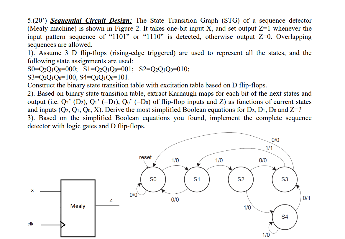
Question: 5 . ( 2 0 ' ) Sequential Circuit Design: The State Transition Graph ( STG ) of a sequence detector ( Mealy machine )
Sequential Circuit Design: The State Transition Graph STG of a sequence detector Mealy machine is shown in Figure It takes onebit input and set output whenever the input pattern sequence of or is detected, otherwise output Overlapping sequences are allowed.
Assume D flipflops risingedge triggered are used to represent all the states, and the following state assignments are used:
;;;
Construct the binary state transition table with excitation table based on flipflops.
Based on binary state transition table, extract Karnaugh maps for each bit of the next states and output ie of flipflop inputs and as functions of current states and inputs Derive the most simplified Boolean equations for and
Based on the simplified Boolean equations you found, implement the complete sequence detector with logic gates and D flipflops.
Step by Step Solution
There are 3 Steps involved in it
1 Expert Approved Answer
Step: 1 Unlock

Question Has Been Solved by an Expert!
Get step-by-step solutions from verified subject matter experts
Step: 2 Unlock
Step: 3 Unlock