Question
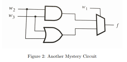
5. Another mystery circuit is shown in Figure 2. Answer the following questions about it. (a) (2) Show the truth table for the function (b)
5. Another mystery circuit is shown in Figure 2. Answer the following questions about it.
(a) (2) Show the truth table for the function
(b) (3) Show how the function could be implemented using a 4-to-1 mux instead.
(c) (2) Based on the number of gates needed for a 4-to-1 mux, which implementation is more efficient: the mystery circuit or your 4-to-1 implementation?
(d) (1) This circuit is called a majority detector. Why?

(e) (8)Write a literal Verilog implementation of the majority detector in the statements above. You must write a separate 2-to-1 mux module that is instantiated by the majority circuit. (To be clear, you must write two modules.) This circuit does not need to be simulated
(f) (8) 7. (8) Write a more behavioral Verilog implementation of the majority detector. Focus on what the circuit does rather than how it does it.
Figure 2: Another Mystery CircuitStep by Step Solution
There are 3 Steps involved in it
Step: 1

Get Instant Access to Expert-Tailored Solutions
See step-by-step solutions with expert insights and AI powered tools for academic success
Step: 2

Step: 3

Ace Your Homework with AI
Get the answers you need in no time with our AI-driven, step-by-step assistance
Get Started


