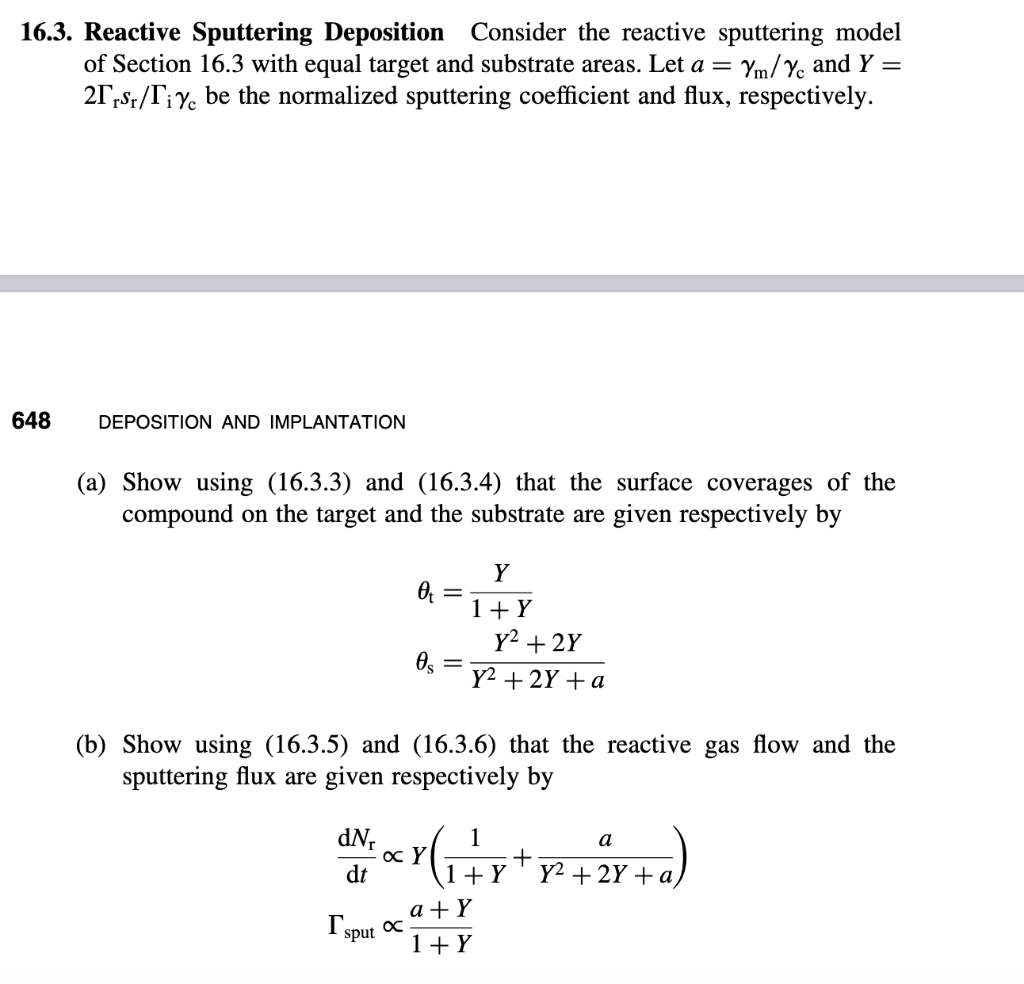
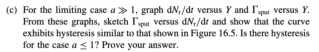
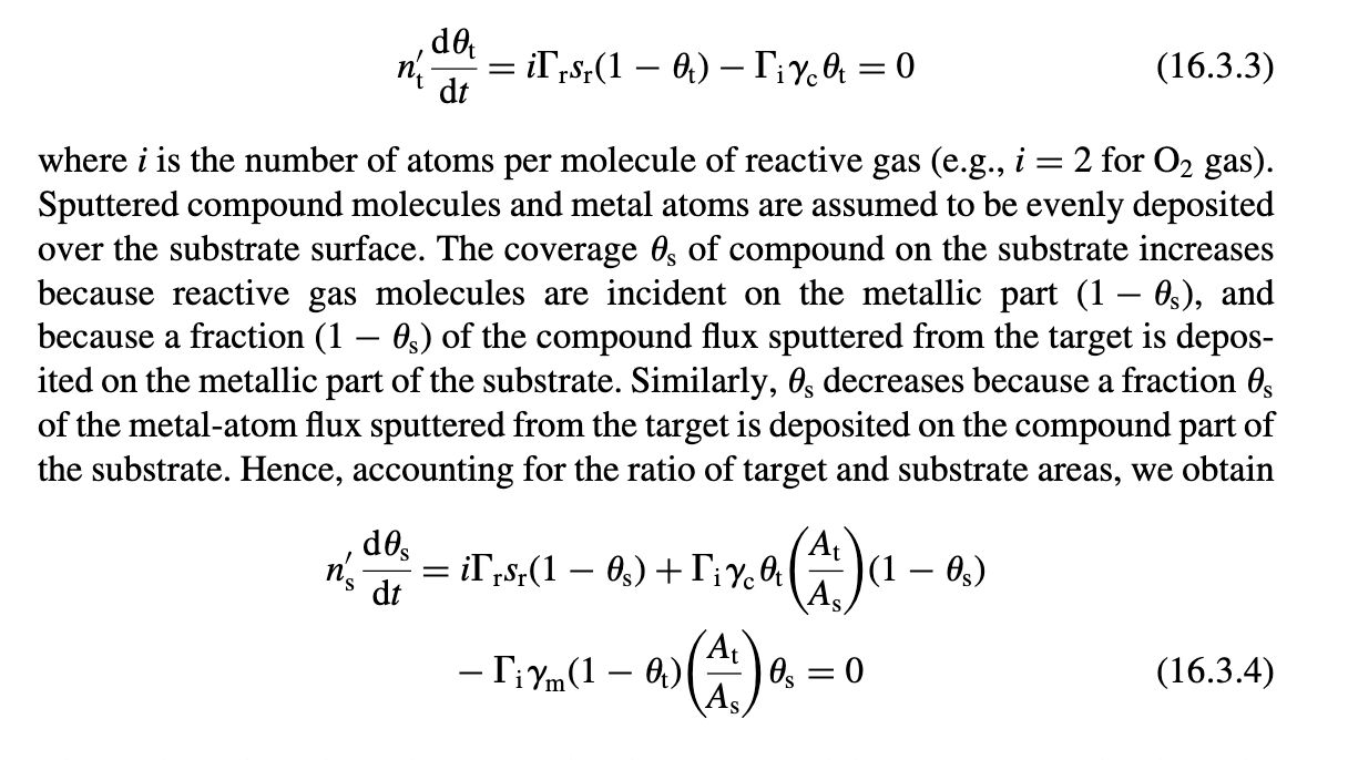
6.3. Reactive Sputtering Deposition Consider the reactive sputtering model of Section 16.3 with equal target and substrate areas. Let a=m/c and Y= 2rsr/ic be the normalized sputtering coefficient and flux, respectively. DEPOSITION AND IMPLANTATION (a) Show using (16.3.3) and (16.3.4) that the surface coverages of the compound on the target and the substrate are given respectively by ts=1+YY=Y2+2Y+aY2+2Y (b) Show using (16.3.5) and (16.3.6) that the reactive gas flow and the sputtering flux are given respectively by dtdNrsputY(1+Y1+Y2+2Y+aa)1+Ya+Y c) For the limiting case a1, graph dNr/dt versus Y and sput versus Y. From these graphs, sketch sput versus dNr/dt and show that the curve exhibits hysteresis similar to that shown in Figure 16.5. Is there hysteresis for the case a1 ? Prove your answer. ntdtdt=irsr(1t)ict=0 where i is the number of atoms per molecule of reactive gas (e.g., i=2 for O2 gas). Sputtered compound molecules and metal atoms are assumed to be evenly deposited over the substrate surface. The coverage s of compound on the substrate increases because reactive gas molecules are incident on the metallic part (1S), and because a fraction (1s) of the compound flux sputtered from the target is deposited on the metallic part of the substrate. Similarly, s decreases because a fraction s of the metal-atom flux sputtered from the target is deposited on the compound part of the substrate. Hence, accounting for the ratio of target and substrate areas, we obtain nsdtds=irsr(1s)+ict(AsAt)(1s)im(1t)(AsAt)s=0 6.3. Reactive Sputtering Deposition Consider the reactive sputtering model of Section 16.3 with equal target and substrate areas. Let a=m/c and Y= 2rsr/ic be the normalized sputtering coefficient and flux, respectively. DEPOSITION AND IMPLANTATION (a) Show using (16.3.3) and (16.3.4) that the surface coverages of the compound on the target and the substrate are given respectively by ts=1+YY=Y2+2Y+aY2+2Y (b) Show using (16.3.5) and (16.3.6) that the reactive gas flow and the sputtering flux are given respectively by dtdNrsputY(1+Y1+Y2+2Y+aa)1+Ya+Y c) For the limiting case a1, graph dNr/dt versus Y and sput versus Y. From these graphs, sketch sput versus dNr/dt and show that the curve exhibits hysteresis similar to that shown in Figure 16.5. Is there hysteresis for the case a1 ? Prove your answer. ntdtdt=irsr(1t)ict=0 where i is the number of atoms per molecule of reactive gas (e.g., i=2 for O2 gas). Sputtered compound molecules and metal atoms are assumed to be evenly deposited over the substrate surface. The coverage s of compound on the substrate increases because reactive gas molecules are incident on the metallic part (1S), and because a fraction (1s) of the compound flux sputtered from the target is deposited on the metallic part of the substrate. Similarly, s decreases because a fraction s of the metal-atom flux sputtered from the target is deposited on the compound part of the substrate. Hence, accounting for the ratio of target and substrate areas, we obtain nsdtds=irsr(1s)+ict(AsAt)(1s)im(1t)(AsAt)s=0