

Answered step by step
Verified Expert Solution
Question
1 Approved Answer
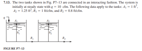
7.13. The two tanks shown in Fig. P7-13 are connected in an interacting fashion. The system is initially at steady state with q=10cfm. The following
Step by Step Solution
There are 3 Steps involved in it
Step: 1

Get Instant Access to Expert-Tailored Solutions
See step-by-step solutions with expert insights and AI powered tools for academic success
Step: 2

Step: 3
Ace Your Homework with AI
Get the answers you need in no time with our AI-driven, step-by-step assistance
Get Started
Fundamentals Of Momentum Heat And Mass Transfer
Authors: James Welty, Gregory L. Rorrer, David G. Foster
6th Edition
1118947460, 978-1118947463