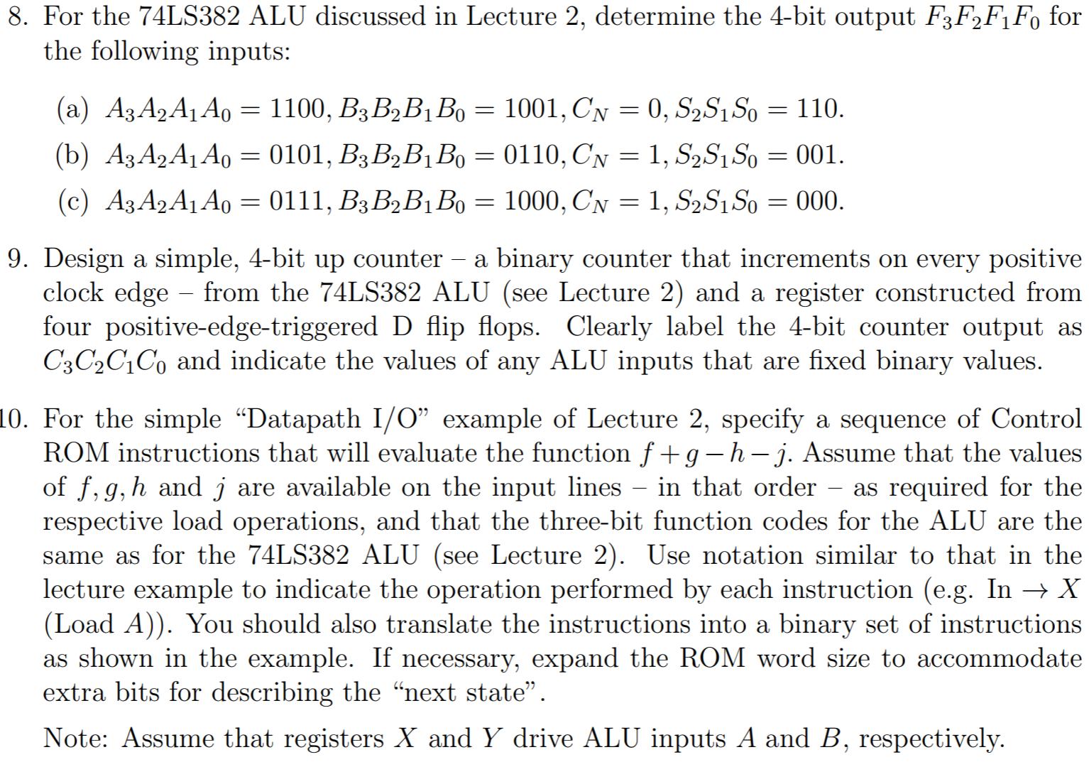
8. For the 74LS382 ALU discussed in Lecture 2, determine the 4-bit output F3 F2F1 Fo for the following inputs: 9. Design a simple, 4-bit up counter - a binary counter that increments on every positive clock edge from the 74LS382 ALU (see Lecture 2) and a register constructed from four positive-edge-triggered D flip flops. Clearly label the 4-bit counter output as C3C2C1Co and indicate the values of any ALU inputs that are fixed binary values. 10. For the simple "Datapath I/O" example of Lecture 2, specify a sequence of Control ROM instructions that will evaluate the function f +g-h - j. Assume that the values of f. q,h and j are available on the input lines - in that order - as required for the respective load operations, and that the three-bit function codes for the ALU are the same as for the74LS382 ALU (see Lecture 2). Use notation similar to that in the lecture example to indicate the operation performed by each instruction (e.g. In X (Load A)). You should also translate the instructions into a binary set of instructions If necessary, expand the ROM word size to extra bits for describing the "next state Note: Assume that registers X and Y drive ALU inputs A and B, respectively 8. For the 74LS382 ALU discussed in Lecture 2, determine the 4-bit output F3 F2F1 Fo for the following inputs: 9. Design a simple, 4-bit up counter - a binary counter that increments on every positive clock edge from the 74LS382 ALU (see Lecture 2) and a register constructed from four positive-edge-triggered D flip flops. Clearly label the 4-bit counter output as C3C2C1Co and indicate the values of any ALU inputs that are fixed binary values. 10. For the simple "Datapath I/O" example of Lecture 2, specify a sequence of Control ROM instructions that will evaluate the function f +g-h - j. Assume that the values of f. q,h and j are available on the input lines - in that order - as required for the respective load operations, and that the three-bit function codes for the ALU are the same as for the74LS382 ALU (see Lecture 2). Use notation similar to that in the lecture example to indicate the operation performed by each instruction (e.g. In X (Load A)). You should also translate the instructions into a binary set of instructions If necessary, expand the ROM word size to extra bits for describing the "next state Note: Assume that registers X and Y drive ALU inputs A and B, respectively


