

Question: A . 1 Fast Constant Multiplier ( There are two pictures, please help finish all the parts ) A constant multiplier of fixed point numbers
A Fast Constant Multiplier There are two pictures, please help finish all the parts
A constant multiplier of fixed point numbers can be implemented by a series of shiftandadd operation.
In this question, you will design a high performance constant multiplier that implements:
y d
where d is an bit unsigned number in signal d: and y is a bit unsigned number y:
For this question, use the following timing information:
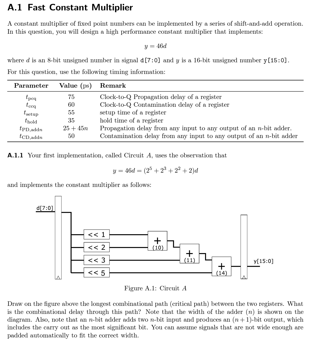
A Your first implementation, called Circuit A uses the observation that
y dd
and implements the constant multiplier as follows:
Draw on the figure above the longest combinational path critical path between the two registers. What
is the combinational delay through this path? Note that the width of the adder n is shown on the
diagram. Also, note that an nbit adder adds two nbit input and produces an nbit output, which
includes the carry out as the most significant bit. You can assume signals that are not wide enough are
padded automatically to fit the correct width. A Taking into account the setup and hold time of the registers, what is the highest clock rate that Circuit A above can run at
A Instead of decomposing the constant into the way shown in Part a it may alternatively be decomposed in the following two ways:
Circuit B: leftrightleftright
Circuit C:
Note the grouping of operation above and how they may affect the order of computation. Also, you can assume you can use the adder for subtraction, which will incur the same delay. Based on the above different ways of decomposing the constant In the following space, sketch the two circuit Circuit B and C that correspond to the two decompositions. Both circuits should have only one layer of input and one output register similar to Circuit A Clearly label the width of the adder and the width of the buses.
A Focusing on just Circuit A your project partner suggests that using all adders of the same width can result in circuit that runs at the same throughput as ones that run with adders of different width. Is your partner correct? Demonstrate your answer by designing a circuit similar to Circuit A but by using only adders of the same width. Clearly label the width of your adders. What is the maximum circle that this circuit may operate at
A Based on the above observations, either by designing a new circuit typology yourself as circuit D or by using the above Circuit A B C with optional pipeline registers inserted, construction designs: i with highest throughput, and ii with lowest latency.
Step by Step Solution
There are 3 Steps involved in it
1 Expert Approved Answer
Step: 1 Unlock

Question Has Been Solved by an Expert!
Get step-by-step solutions from verified subject matter experts
Step: 2 Unlock
Step: 3 Unlock