Answered step by step
Verified Expert Solution
Question
1 Approved Answer
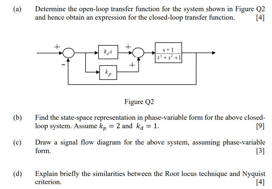
(a) (b) (c) (d) Determine the open-loop transfer function for the system shown in Figure Q2 and hence obtain an expression for the closed-loop

(a) (b) (c) (d) Determine the open-loop transfer function for the system shown in Figure Q2 and hence obtain an expression for the closed-loop transfer function. [4] kas C + s+1 S +5 +1 Figure Q2 Find the state-space representation in phase-variable form for the above closed- loop system. Assume kp = 2 and ka = 1. [9] Draw a signal flow diagram for the above system, assuming phase-variable form. [3] Explain briefly the similarities between the Root locus technique and Nyquist criterion. [4]
Step by Step Solution
★★★★★
3.43 Rating (156 Votes )
There are 3 Steps involved in it
Step: 1
Lets take it step by step a OpenLoop Transfer Function The openloop transfer function of the given system is the product of the transfer functions of the individual components in the forward path For ...
Get Instant Access to Expert-Tailored Solutions
See step-by-step solutions with expert insights and AI powered tools for academic success
Step: 2

Step: 3

Ace Your Homework with AI
Get the answers you need in no time with our AI-driven, step-by-step assistance
Get Started


