

Question
A circuit with PIC18F4550 microcontroller is interfaced to a DAC0808 and an Op-Amp as shown in the figure above. A program written in assembly language
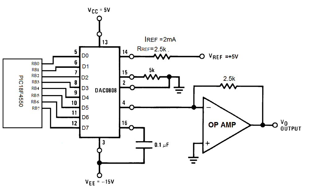
A circuit with PIC18F4550 microcontroller is interfaced to a DAC0808 and an Op-Amp as shown in the figure above.
A program written in assembly language targeted for the circuit above is listed as below:
ORG 0000H
CNT1 EQU 0x30 ; 0x30 is the location for CNT1
CLRF TRISB, 1 ; Set to output
MOVLW 0x01
MOVWF PORTB
LOOP1: MOVLW 0b11001
MOVWF CNT1 ; Put this binary no. into CNT1
LOOP2: RLNCF PORTB, 1, 0 ; Rotate Left
DECF CNT1, 1, 0 ; Decrement CNT1
BNZ LOOP2 ; Jump to LOOP2 if not zero
BRA LOOP1 ; Jump to LOOP1
END: ; End of program
The crystal frequency is 16MHz and each instruction takes 4 cycles to execute.
The output voltage range of the DAC is set to between 0-5V.
Based on the circuit, program and the given conditions,
(a) Sketch and label the output waveform of this circuit for 2 cycles. Show the necessary calculations.
(b) Rewrite the given program in C language. Show only the main function. Use the library function Delay10TCY(x) to generate the desired delay.
IREF 2mA RREF 2.5k 3 14 DO D1 D2 D3 DAC0808 D4 D5 D6 D7 VREF +5V RB0 RB1 U RB2 15 5k 2.5k 00 RB4 URB6 0 12 6 OP AMP 0 OUTPUT 3 VEE-15V
Step by Step Solution
There are 3 Steps involved in it
Step: 1

Get Instant Access to Expert-Tailored Solutions
See step-by-step solutions with expert insights and AI powered tools for academic success
Step: 2

Step: 3
Ace Your Homework with AI
Get the answers you need in no time with our AI-driven, step-by-step assistance
Get Started
Oracle9i Database Administrator Implementation And Administration
Authors: Carol McCullough-Dieter
1st Edition
0619159006, 978-0619159009