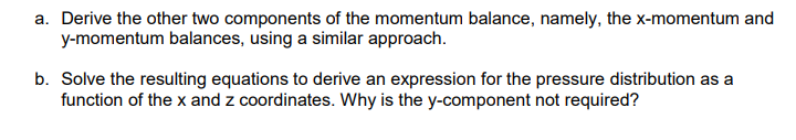
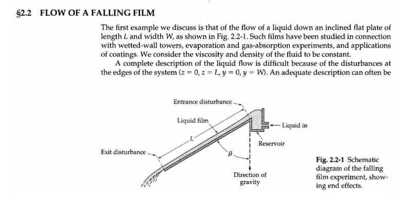
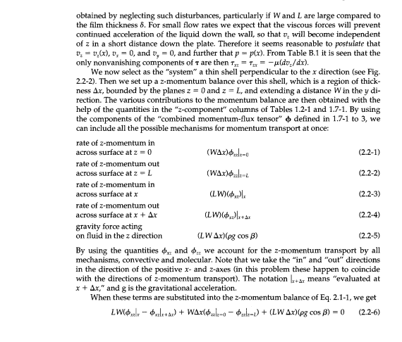
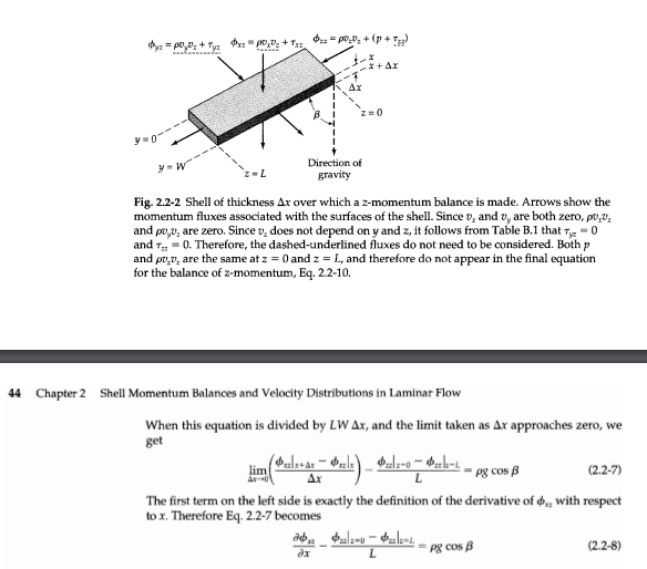
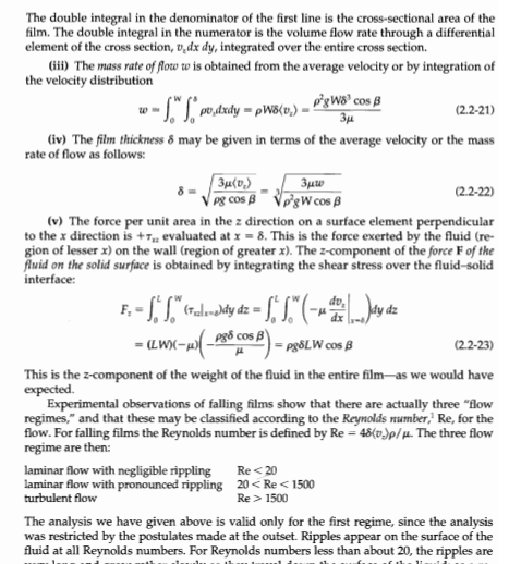
a. Derive the other two components of the momentum balance, namely, the x-momentum and y-momentum balances, using a similar approach. b. Solve the resulting equations to derive an expression for the pressure distribution as a function of the x and z coordinates. Why is the y-component not required? $2.2 FLOW OF A FALLING FILM The first example we discuss is that of the flow of a liquid down an inclined flat plate of length L and width W, as shown in Fig. 2.2-1. Such films have been studied in connection with wetted-wall towers, evaporation and gas-absorption experiments, and applications of coatings. We consider the viscosity and density of the fluid to be constant. A complete description of the liquid flow is difficult because of the disturbances at the edges of the system (z = 0, z = L, y = 0, y = W). An adequate description can often be Entrance disturbance Liquid film -Liquid in Reservoir Exit disturbance Direction of gravity Fig. 2.2-1 Schematic diagram of the falling film experiment, show- ing end effects. obtained by neglecting such disturbances, particularly if Wand L are large compared to the film thickness 8. For small flow rates we expect that the viscous forces will prevent continued acceleration of the liquid down the wall, so that 7, will become independent of z in a short distance down the plate. Therefore it seems reasonable to postulate that 0. = 0,(x), 0, = 0, and 0, = 0, and further that p = p(x). From Table B.1 it is seen that the only nonvanishing components of T are then tx=-uldv./dx). We now select as the "system" a thin shell perpendicular to the x direction (see Fig. 2.2-2). Then we set up a z-momentum balance over this shell, which is a region of thick- ness Ax, bounded by the planes z = 0 and z = L, and extending a distance W in the y di- rection. The various contributions to the momentum balance are then obtained with the help of the quantities in the z-component" columns of Tables 1.2-1 and 1.7-1. By using the components of the "combined momentum-flux tensor" defined in 1.7-1 to 3, we can include all the possible mechanisms for momentum transport at once: rate of z-momentum in across surface at z = 0 (WAx) (2.2-1) rate of z-momentum out across surface at 2 -L (WAx) - (2.2-2) rate of z-momentum in across surface at x (LW) (2.2-3) rate of z-momentum out across surface at x + Ar (LW...ta: (2.2-4) gravity force acting on fluid in the z direction (LW 4x)(pg cos B) (2.2-5) By using the quantities and d. we account for the 2-momentum transport by all mechanisms, convective and molecular. Note that we take the "in" and "out" directions in the direction of the positive x-and z-axes (in this problem these happen to coincide with the directions of z-momentum transport). The notation Ix+ar means "evaluated at x + Ax," and g is the gravitational acceleration. When these terms are substituted into the x-momentum balance of Eq.2.1-1, we get LWOzelo - 3+as) + WAxl0x1-0 - zdlz-1) + (LW Ax)(pg cos B) = 0 (2.2-6) 1+ 0.2 = PP,D+ (p+ Tw 2 = 0,03 + Ty xz po, o + Trz + r Ax Z=0 w Direction of gravity Fig. 2.2-2 Shell of thickness Ax over which a z-momentum balance is made. Arrows show the momentum fluxes associated with the surfaces of the shell. Since v, and vy are both zero, po,0z and poo, are zero. Sincev, does not depend on y and z, it follows from Table B.1 that Tye - 0 and T = 0. Therefore, the dashed-underlined fluxes do not need to be considered. Both p and pu.v, are the same at z = 0 and z = L, and therefore do not appear in the final equation for the balance of z-momentum, Eq.2.2-10. 44 Chapter 2 Shell Momentum Balances and Velocity Distributions in Laminar Flow L When this equation is divided by LW Ax, and the limit taken as Ax approaches zero, we get &clx+ar - Oulxal-o-al- lim * Pg cos B (2.2-7) The first term on the left side is exactly the definition of the derivative of with respect tox. Therefore Eq. 2.2-7 becomes de $ulz-v - 622-4 =Pg cos B (2.2-8) dx L At this point we have to write out explicitly what the components, and are, mak- ing use of the definition of din Eqs. 1.7-1 to 3 and the expressions for to and f, in Ap- pendix B.1. This ensures that we do not miss out on any of the forms of momentum transport. Hence we get au, T + po,p, ax + pu.. (2.2-9a) 20. $a = p + 9+ p0.0: - p - 24 zz + p.V. (2.2-95) In accordance with the postulates that v, = 0,(x), 0, 0, 0, 0, and p - P(x), we see that (i) since v, = 0, the poo, term in Eq. 2.2-9a is zero; (ii) since v = 0,(x), the term -2ulov./az) in Eq. 2.2.95 is zero; (iii) since v. = v(x), the term p0,0, is the same at 2 - 0 and z = L; and (iv) since p = p(x), the contribution p is the same at z = 0 and z L. Hence T, depends only on x, and Eq. 2.2-8 simplifies to dr. Pg cos B (2.2-10) This is the differential equation for the momentum flux 7,. It may be integrated to give -- (eg cos B)x+C (2.2-11) The constant of integration may be evaluated by using the boundary condition at the gas-liquid interface (see $2.1): B.C. 1: at x = 0, -0 (2.2-12) Substitution of this boundary condition into Eq.2.2-11 shows that C = 0. Therefore the momentum-flux distribution is 1.- (og cos B)x (2.2-13) as shown in Fig. 2.2-3. Next we substitute Newton's law of viscosity du (2.2-14) into the left side of Eq. 2.2-13 to obtain du. pg CO B els (2.2-15) which is the differential equation for the velocity distribution. It can be integrated to give --()+63 Pg (2.2-16) 2 $2.2 Flow of a Falling Film 45 Velocity distribution x) Ax Momentum flux distribution T) Direction of gravity Fig. 2.2-3 Final results for the falling film problem, showing the momentum-flux distribution and the velocity distribution. The shell of thickness Ax, over which the momentum balance was made, is also shown. The constant of integration is evaluated by using the no-slip boundary condition at the solid surface: B.C. 2 at x = 8, 0.0 (2.2-17) The double integral in the denominator of the first line is the cross-sectional area of the film. The double integral in the numerator is the volume flow rate through a differential element of the cross section, v dx dy, integrated over the entire cross section. (iii) The mass rate of flow w is obtained from the average velocity or by integration of the velocity distribution w -- "Spodxdy pW8(0,) - p?gW8 cos B 34 (2.2-21) (iv) The film thickness & may be given in terms of the average velocity or the mass rate of flow as follows: 3(0) 3uw pg cos pgWcos B (2.2-22) (v) The force per unit area in the z direction on a surface element perpendicular to the x direction is +1 evaluated at x = 8. This is the force exerted by the fluid (re- gion of lesser x) on the wall (region of greater x). The 2-component of the force F of the fluid on the solid surface is obtained by integrating the shear stress over the fluid-solid interface: do, F:-ST."(celmddy dz = - SS"(- )dy dz = [ww-wl_2188.com) B) Pg8LW cos B (2.2-23) This is the z-component of the weight of the fluid in the entire filmas we would have expected Experimental observations of falling films show that there are actually three "flow regimes," and that these may be classified according to the Reynolds rumber, Re, for the flow. For falling films the Reynolds number is defined by Re = 48(v.)p/. The three flow regime are then: laminar flow with negligible rippling Re 1500 The analysis we have given above is valid only for the first regime, since the analysis was restricted by the postulates made at the outset. Ripples appear on the surface of the fluid at all Reynolds numbers. For Reynolds numbers less than about 20, the ripples are a. Derive the other two components of the momentum balance, namely, the x-momentum and y-momentum balances, using a similar approach. b. Solve the resulting equations to derive an expression for the pressure distribution as a function of the x and z coordinates. Why is the y-component not required? $2.2 FLOW OF A FALLING FILM The first example we discuss is that of the flow of a liquid down an inclined flat plate of length L and width W, as shown in Fig. 2.2-1. Such films have been studied in connection with wetted-wall towers, evaporation and gas-absorption experiments, and applications of coatings. We consider the viscosity and density of the fluid to be constant. A complete description of the liquid flow is difficult because of the disturbances at the edges of the system (z = 0, z = L, y = 0, y = W). An adequate description can often be Entrance disturbance Liquid film -Liquid in Reservoir Exit disturbance Direction of gravity Fig. 2.2-1 Schematic diagram of the falling film experiment, show- ing end effects. obtained by neglecting such disturbances, particularly if Wand L are large compared to the film thickness 8. For small flow rates we expect that the viscous forces will prevent continued acceleration of the liquid down the wall, so that 7, will become independent of z in a short distance down the plate. Therefore it seems reasonable to postulate that 0. = 0,(x), 0, = 0, and 0, = 0, and further that p = p(x). From Table B.1 it is seen that the only nonvanishing components of T are then tx=-uldv./dx). We now select as the "system" a thin shell perpendicular to the x direction (see Fig. 2.2-2). Then we set up a z-momentum balance over this shell, which is a region of thick- ness Ax, bounded by the planes z = 0 and z = L, and extending a distance W in the y di- rection. The various contributions to the momentum balance are then obtained with the help of the quantities in the z-component" columns of Tables 1.2-1 and 1.7-1. By using the components of the "combined momentum-flux tensor" defined in 1.7-1 to 3, we can include all the possible mechanisms for momentum transport at once: rate of z-momentum in across surface at z = 0 (WAx) (2.2-1) rate of z-momentum out across surface at 2 -L (WAx) - (2.2-2) rate of z-momentum in across surface at x (LW) (2.2-3) rate of z-momentum out across surface at x + Ar (LW...ta: (2.2-4) gravity force acting on fluid in the z direction (LW 4x)(pg cos B) (2.2-5) By using the quantities and d. we account for the 2-momentum transport by all mechanisms, convective and molecular. Note that we take the "in" and "out" directions in the direction of the positive x-and z-axes (in this problem these happen to coincide with the directions of z-momentum transport). The notation Ix+ar means "evaluated at x + Ax," and g is the gravitational acceleration. When these terms are substituted into the x-momentum balance of Eq.2.1-1, we get LWOzelo - 3+as) + WAxl0x1-0 - zdlz-1) + (LW Ax)(pg cos B) = 0 (2.2-6) 1+ 0.2 = PP,D+ (p+ Tw 2 = 0,03 + Ty xz po, o + Trz + r Ax Z=0 w Direction of gravity Fig. 2.2-2 Shell of thickness Ax over which a z-momentum balance is made. Arrows show the momentum fluxes associated with the surfaces of the shell. Since v, and vy are both zero, po,0z and poo, are zero. Sincev, does not depend on y and z, it follows from Table B.1 that Tye - 0 and T = 0. Therefore, the dashed-underlined fluxes do not need to be considered. Both p and pu.v, are the same at z = 0 and z = L, and therefore do not appear in the final equation for the balance of z-momentum, Eq.2.2-10. 44 Chapter 2 Shell Momentum Balances and Velocity Distributions in Laminar Flow L When this equation is divided by LW Ax, and the limit taken as Ax approaches zero, we get &clx+ar - Oulxal-o-al- lim * Pg cos B (2.2-7) The first term on the left side is exactly the definition of the derivative of with respect tox. Therefore Eq. 2.2-7 becomes de $ulz-v - 622-4 =Pg cos B (2.2-8) dx L At this point we have to write out explicitly what the components, and are, mak- ing use of the definition of din Eqs. 1.7-1 to 3 and the expressions for to and f, in Ap- pendix B.1. This ensures that we do not miss out on any of the forms of momentum transport. Hence we get au, T + po,p, ax + pu.. (2.2-9a) 20. $a = p + 9+ p0.0: - p - 24 zz + p.V. (2.2-95) In accordance with the postulates that v, = 0,(x), 0, 0, 0, 0, and p - P(x), we see that (i) since v, = 0, the poo, term in Eq. 2.2-9a is zero; (ii) since v = 0,(x), the term -2ulov./az) in Eq. 2.2.95 is zero; (iii) since v. = v(x), the term p0,0, is the same at 2 - 0 and z = L; and (iv) since p = p(x), the contribution p is the same at z = 0 and z L. Hence T, depends only on x, and Eq. 2.2-8 simplifies to dr. Pg cos B (2.2-10) This is the differential equation for the momentum flux 7,. It may be integrated to give -- (eg cos B)x+C (2.2-11) The constant of integration may be evaluated by using the boundary condition at the gas-liquid interface (see $2.1): B.C. 1: at x = 0, -0 (2.2-12) Substitution of this boundary condition into Eq.2.2-11 shows that C = 0. Therefore the momentum-flux distribution is 1.- (og cos B)x (2.2-13) as shown in Fig. 2.2-3. Next we substitute Newton's law of viscosity du (2.2-14) into the left side of Eq. 2.2-13 to obtain du. pg CO B els (2.2-15) which is the differential equation for the velocity distribution. It can be integrated to give --()+63 Pg (2.2-16) 2 $2.2 Flow of a Falling Film 45 Velocity distribution x) Ax Momentum flux distribution T) Direction of gravity Fig. 2.2-3 Final results for the falling film problem, showing the momentum-flux distribution and the velocity distribution. The shell of thickness Ax, over which the momentum balance was made, is also shown. The constant of integration is evaluated by using the no-slip boundary condition at the solid surface: B.C. 2 at x = 8, 0.0 (2.2-17) The double integral in the denominator of the first line is the cross-sectional area of the film. The double integral in the numerator is the volume flow rate through a differential element of the cross section, v dx dy, integrated over the entire cross section. (iii) The mass rate of flow w is obtained from the average velocity or by integration of the velocity distribution w -- "Spodxdy pW8(0,) - p?gW8 cos B 34 (2.2-21) (iv) The film thickness & may be given in terms of the average velocity or the mass rate of flow as follows: 3(0) 3uw pg cos pgWcos B (2.2-22) (v) The force per unit area in the z direction on a surface element perpendicular to the x direction is +1 evaluated at x = 8. This is the force exerted by the fluid (re- gion of lesser x) on the wall (region of greater x). The 2-component of the force F of the fluid on the solid surface is obtained by integrating the shear stress over the fluid-solid interface: do, F:-ST."(celmddy dz = - SS"(- )dy dz = [ww-wl_2188.com) B) Pg8LW cos B (2.2-23) This is the z-component of the weight of the fluid in the entire filmas we would have expected Experimental observations of falling films show that there are actually three "flow regimes," and that these may be classified according to the Reynolds rumber, Re, for the flow. For falling films the Reynolds number is defined by Re = 48(v.)p/. The three flow regime are then: laminar flow with negligible rippling Re 1500 The analysis we have given above is valid only for the first regime, since the analysis was restricted by the postulates made at the outset. Ripples appear on the surface of the fluid at all Reynolds numbers. For Reynolds numbers less than about 20, the ripples are