Answered step by step
Verified Expert Solution
Question
1 Approved Answer
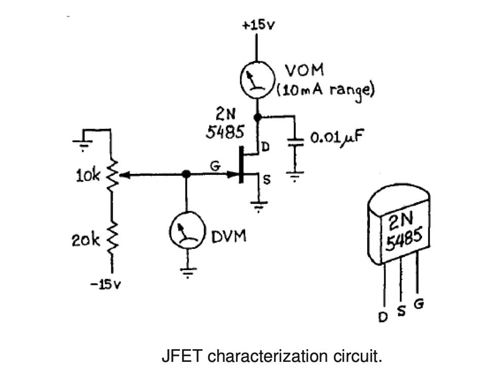
(a) Using MultiSIM construct the circuit below designed to measure the characteristic parameters of a JFET, specifically you will determine the drain- source current


(a) Using MultiSIM construct the circuit below designed to measure the characteristic parameters of a JFET, specifically you will determine the drain- source current with gate shorted to source IDS S, the pinch-off voltage Vp, and the general drain current ID versus gate-source voltage VGS behavior. Attach a copy of your d (b)Record the drain current ID for the following gate-source voltage values: (0, -0.5, -1, -1.5, -2, -2.5, and -2.75) volts. If the drain current "pinches off" lower (or higher) than -2.75 V then use that value instead. In other words, try to precisely find the voltage at which the drain current tends to zero, this voltage is the pinch-off voltage Vp. Plot ID versus VGS using a graphing program, e.g., Origin, Excel, or Mathematica. Plot both a linear graph and log of drain current versus linear voltage. (c)Fit the data to the empirical model and extract the coefficients (i.e., fit parameters) IDSS and Vp. Recall ID = (IDSS /Vp^2 )(VGS -Vp)^2 Include the fit results, i.e., plot the above function with the resulting fit parameter values for IDS S and Vp into both of your graphs from part (b). Label IDS S and Vp on your graph and indicate their values. PS:REPLY TO a,b,c the best you can 10k 20k -15 v +15v 2N 5485 G DVM VOM (10mA range) 0.01 F 2N 5485 JFET characterization circuit. G
Step by Step Solution
★★★★★
3.50 Rating (150 Votes )
There are 3 Steps involved in it
Step: 1
a Using MultiSIM a circuit can be constructed to measure the characteristic parameters of a JFET jun...
Get Instant Access to Expert-Tailored Solutions
See step-by-step solutions with expert insights and AI powered tools for academic success
Step: 2

Step: 3

Ace Your Homework with AI
Get the answers you need in no time with our AI-driven, step-by-step assistance
Get Started


