Question
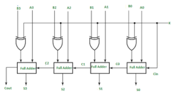
Adder/Subtractor Using four of your full adder components (described above), in a separate circuit (called ADD_SUB) create a 4-bit adder/subtractor component. The circuit will take
Adder/Subtractor
Using four of your full adder components (described above), in a separate circuit (called ADD_SUB) create a 4-bit adder/subtractor component. The circuit will take two sets of 4-bit inputs (A3-A0 and B3-B0), plus two additional inputs SUB (if true, SUBTRACT, otherwise ADD) and ENABLE (if true, all outputs are enabled using tri-state buffers, if false, all outputs are disabled). The circuit will produce a 4-bit sum (S3-S0) or difference (when subtracting).
The basic circuit is given below (without the ENABLE input). In this circuit, the K input is the same as our SUB input.

Step by Step Solution
There are 3 Steps involved in it
Step: 1

Get Instant Access to Expert-Tailored Solutions
See step-by-step solutions with expert insights and AI powered tools for academic success
Step: 2

Step: 3

Ace Your Homework with AI
Get the answers you need in no time with our AI-driven, step-by-step assistance
Get Started


