Answered step by step
Verified Expert Solution
Question
1 Approved Answer
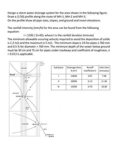
Design a storm water drainage system for the area shown in the following figure. Draw a (1:50) profile along the route of MH-1, MH-2

Design a storm water drainage system for the area shown in the following figure. Draw a (1:50) profile along the route of MH-1, MH-2 and MH-3. On the profile show all pipe sizes, slopes, and ground and invert elevations. The rainfall intensity (mm/h) for the area can be found from the following equation: i=1100/(t+45); where t is the rainfall duration (minute) The minimum allowable scouring velocity required to avoid the deposition of solids is 1.2 m/s and the maximum is 5 m/s. The minimum slope is 1% for pipes 760 mm and 0.5 % for diameter > 760 mm. The minimum depth of the sewer below ground must be 30 cm and 75 cm for pipes under roadways and coefficient of roughness, n = 0.013 is applicable. Road GE-945 133M ***** 300 M rema pon GE-83M Oll Sub-basin 1 11 111 Drainage Area A (m) 14000 20000 13500 Runoff Coefficient C 0,42 0.10 0.70 Inlet time (minutes) 7.00 11.00 10.00
Step by Step Solution
★★★★★
3.45 Rating (161 Votes )
There are 3 Steps involved in it
Step: 1
The image shows instructions for designing a stormwater drainage system for three subbasins labeled MH1 MH2 and MH3 It includes a table with the subba...
Get Instant Access to Expert-Tailored Solutions
See step-by-step solutions with expert insights and AI powered tools for academic success
Step: 2

Step: 3

Ace Your Homework with AI
Get the answers you need in no time with our AI-driven, step-by-step assistance
Get Started


