Answered step by step
Verified Expert Solution
Question
1 Approved Answer
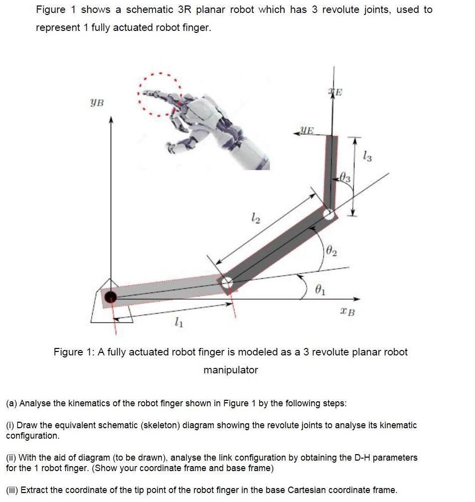
Figure 1 shows a schematic 3R planar robot which has 3 revolute joints, used to represent 1 fully actuated robot finger. YB 1 YE

Figure 1 shows a schematic 3R planar robot which has 3 revolute joints, used to represent 1 fully actuated robot finger. YB 1 YE E L03 XB Figure 1: A fully actuated robot finger is modeled as a 3 revolute planar robot manipulator (a) Analyse the kinematics of the robot finger shown in Figure 1 by the following steps: (i) Draw the equivalent schematic (skeleton) diagram showing the revolute joints to analyse its kinematic configuration. (ii) With the aid of diagram (to be drawn), analyse the link configuration by obtaining the D-H parameters for the 1 robot finger. (Show your coordinate frame and base frame) (iii) Extract the coordinate of the tip point of the robot finger in the base Cartesian coordinate frame.
Step by Step Solution
★★★★★
3.40 Rating (153 Votes )
There are 3 Steps involved in it
Step: 1
Certainly a more professional approach to solving the kinematics of the 3R planar robot finger in the image can be achieved through the following step...
Get Instant Access to Expert-Tailored Solutions
See step-by-step solutions with expert insights and AI powered tools for academic success
Step: 2

Step: 3

Ace Your Homework with AI
Get the answers you need in no time with our AI-driven, step-by-step assistance
Get Started


