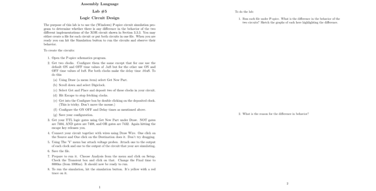
Question: Assembly Language Lab # 5 Logic Circuit Design The purpose of this lab is to use the ( Windows ) P - spice circuit simulation
Assembly Language
Lab #
Logic Circuit Design
The purpose of this lab is to use the Windows Pspice circuit simulation program to determine whether there is any difference in the behavior of the two different implementations of the XOR circuit shown in Section You may either create a file for each circuit or put both circuits in one file. When you are ready you can hit the Simulation button to run the circuits and observe their behavior.
To create the circuits:
Open the Pspice schematics program.
Get two clocks. Configure them the same except that for one use the default and OFF time values of uS but for the other use ON and OFF time values of For both clocks make the delay time uS To do this
a Using Draw a menu item select Get New Part.
b Scroll down and select Digiclock.
c Select Get and Place and deposit two of these clocks in your circuit.
d Hit Escape to stop fetching clocks.
e Get into the Configure box by double clicking on the deposited clock. This is tricky. Don't move the mouse.
f Configure the ON OFF and Delay times as mentioned above.
g Save your configuration.
Get your TTL logic gates using Get New Part under Draw. NOT gates are AND gates are and OR gates are Again hitting the escape key releases you.
Connect your circuit together with wires using Draw Wire. One click on the Source and One click on the Destination does it Don't try dragging.
Using The V menu bar attach voltage probes. Attach one to the output of each clock and one to the output of the circuit that your are simulating.
Save the file.
Prepare to run it Choose Analysis from the menu and click on Setup. Check the Transient box and click on that. Change the Final time to ns from It should now be ready to run.
To run the simulation, hit the simulation button. It's yellow with a red trace on it
To do the labs:
Run each file under spice. What is the difference in the behavior of the two circuits? Slartch the graphs of each here highlighting the difference.
What is the reason for the difference in behavior?

Step by Step Solution
There are 3 Steps involved in it
1 Expert Approved Answer
Step: 1 Unlock


Question Has Been Solved by an Expert!
Get step-by-step solutions from verified subject matter experts
Step: 2 Unlock
Step: 3 Unlock


