Question
Assume that X1 is initialized to 11 and X2 is initialized to 22. Suppose you executed the code below on a version of the pipeline
Assume that X1 is initialized to 11 and X2 is initialized to 22. Suppose you executed the code below on a version of the pipeline from Section 4.5 that does not handle data hazards (i.e., the programmer is responsible for addressing data hazards by inserting NOP instructions where necessary). What would the final values of register X5 be? Assume the register file is written at the beginning of the cycle and read at the end of a cycle. Therefore, an ID stage will return the results of a WB state occurring during the same cycle. See Section 4.7 and Figure 4.51 for details.
ADDI X1, X2, #5 ADD X3, X1, X2 ADDI X4, X1, #15 ADD X5, X1, X1
Figure 4.51 below.
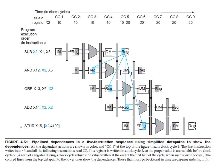
Time (in clock cycles) alue o register X2 10 10 10 10 20 20 20 20 20 Program execution order (in instructions) SUB X2, X1, X3 IM DM AND X12, X2, X5 IM DM ORR X13, X6, X2 IM DM ADD X14, X2, X2 IM DM STUR X15, [X2,#100] IM DM egi FIGURE 4.51 Pipelined dependences in a five-instruction sequence using simplified datapaths to show the dependences. All the dependent actions are shown in color, and "CC 1" at the top of the figure means clock cycle 1. The first instruction writes into X2, and all the following instructions read X2. This register is written in clock cycle 5, so the proper value is unavailable before clock cycle 5. (A read of a register during a clock cycle returns the value written at the end of the first half of the cycle, when such a write occurs.) The colored lines from the top datapath to the lower ones show the dependences. Those that must go backward in time are pipeline data hazards. Time (in clock cycles) alue o register X2 10 10 10 10 20 20 20 20 20 Program execution order (in instructions) SUB X2, X1, X3 IM DM AND X12, X2, X5 IM DM ORR X13, X6, X2 IM DM ADD X14, X2, X2 IM DM STUR X15, [X2,#100] IM DM egi FIGURE 4.51 Pipelined dependences in a five-instruction sequence using simplified datapaths to show the dependences. All the dependent actions are shown in color, and "CC 1" at the top of the figure means clock cycle 1. The first instruction writes into X2, and all the following instructions read X2. This register is written in clock cycle 5, so the proper value is unavailable before clock cycle 5. (A read of a register during a clock cycle returns the value written at the end of the first half of the cycle, when such a write occurs.) The colored lines from the top datapath to the lower ones show the dependences. Those that must go backward in time are pipeline data hazardsStep by Step Solution
There are 3 Steps involved in it
Step: 1
Get Instant Access to Expert-Tailored Solutions
See step-by-step solutions with expert insights and AI powered tools for academic success
Step: 2
Step: 3
Ace Your Homework with AI
Get the answers you need in no time with our AI-driven, step-by-step assistance
Get Started