Question
Based off of the photos provided and sample code..plz edit it to what is required or help give hints. Thanks. Photos: Code: #include int value=0,
Based off of the photos provided and sample code..plz edit it to what is required or help give hints. Thanks.
Photos:


Code:
#include
int value=0, i=0 ; int light = 0, lightroom = 0, dimled=50; int temp = 0, temproom = 0; int touch =0, touchroom =0; int flag =0; int ADCReading [3];
// Function Prototypes void fadeLED(int valuePWM); void ConfigureAdc(void); void getanalogvalues();
int main(void) { WDTCTL = WDTPW + WDTHOLD; // Stop WDT P1OUT = 0; P2OUT = 0; P1DIR = 0; P1REN = 0; P2REN = 0; P2DIR = 0; P1DIR |= ( BIT4 | BIT5 | BIT6); // set bits 4, 5, 6 as outputs P2DIR |= ( BIT0 | BIT1 ); // set bit 0, 1 as outputs
ConfigureAdc();
// reading the initial room values, lightroom, touchroom, temproom __delay_cycles(250); getanalogvalues(); lightroom = light; touchroom = touch; temproom = temp; __delay_cycles(250);
for (;;) { //reading light, touch, and temp repeatedly at the beginning of the main loop getanalogvalues();
//light controlling LED2 on launchpad (P1.6) via variable dimled dimled = light; //use the light reading range limits 50-1000, and conver them to 0-100% dimled = ((dimled- 50)*100)/(1000- 50); if(dimled =95)dimled = 100; fadeLED(dimled);
//Light Controlling a LED on port 2.1 //Observe the dead zone for no action to avoid flickering //I chose the range 1.1 to 1.5 of the value; that is no action if (1.1 lightroom lightroom * 1.10) {} else { if(light >= lightroom * 1.50) {P2OUT |= BIT1; __delay_cycles(200);} // on if dark if(light
//Temp Controlling a LED on port 2.0 //The code below uses a smple comparision which create flickering //Modify the code below to create a dead zon to prevent fleckering //if temp is higher than 1.04 * temproom, turn LED2 on //if temp is lower than 1.02 * temproom, turn LED2 off if(temp > temproom) {P2OUT |= BIT0; __delay_cycles(200);} // SSR on else {P2OUT &= ~BIT0; __delay_cycles(200);} // SSR off
//Touch Controlling Motor Direction //observe the dead zone for no action between 0.07-0.09 of the value temp if(touch > touchroom * 0.7 && touch = touchroom * 0.9) {P1OUT &=~BIT4; P1OUT |= BIT5; __delay_cycles(200);} // set motor FW direction if(touch
}
} }
void ConfigureAdc(void) { ADC10CTL1 = INCH_2 | CONSEQ_1; // A2 + A1 + A0, single sequence ADC10CTL0 = ADC10SHT_2 | MSC | ADC10ON; while (ADC10CTL1 & BUSY); ADC10DTC1 = 0x03; // 3 conversions ADC10AE0 |= (BIT0 | BIT1 | BIT2); // ADC10 option select }
void fadeLED(int valuePWM) { P1SEL |= (BIT6); // P1.0 and P1.6 TA1/2 options CCR0 = 100 - 0; // PWM Period CCTL1 = OUTMOD_3; // CCR1 reset/set CCR1 = valuePWM; // CCR1 PWM duty cycle TACTL = TASSEL_2 + MC_1; // SMCLK, up mode }
void getanalogvalues() { i = 0; temp = 0; light = 0; touch =0; // set all analog values to zero for(i=1; i
#pragma vector=ADC10_VECTOR __interrupt void ADC10_ISR(void) { __bic_SR_register_on_exit(CPUOFF); }
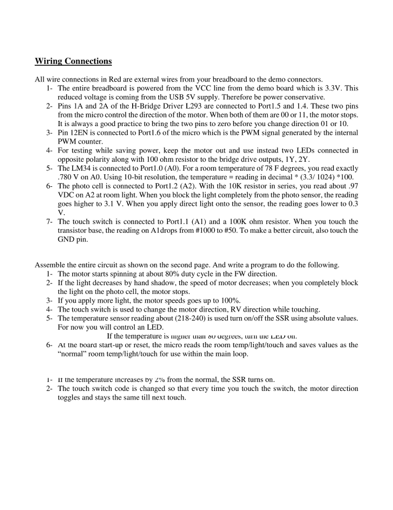
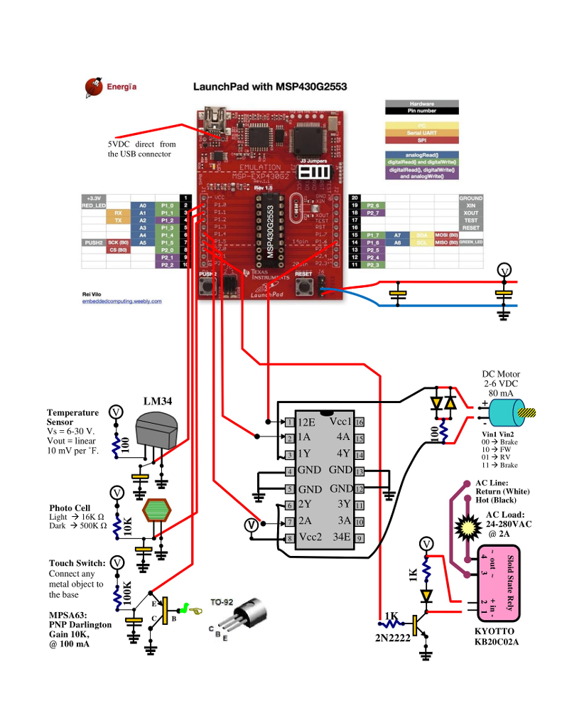
Wiring Connections All wire connections in Red are external wires from your breadboard to the demo connectors. 1- The entire breadboard is powered from the VCC line from the demo board which is 3.3V. This reduced voltage is coming from the USB 5V supply. Therefore be power conservative. 2- Pins 1A and 2A of the H-Bridge Driver L293 are connected to Port1.5 and 1.4. These two pins from the micro control the direction of the motor. When both of them are 00 or 11, the motor stops. 3- Pin 12EN is connected to Port1.6 of the micro which is the PWM signal generated by the internal 4- For testing while saving power, keep the motor out and use instead two LEDs connected in 5- The LM34 is connected to Port1.0 (A0). For a room temperature of 78 F degrees, you read exactly It is always a good practice to bring the two pins to zero before you change direction 01 or 10 PWM counter opposite polarity along with 100 ohm resistor to the bridge drive outputs, IY, 2Y. 780 V on A0. Using 10-b resolution, the temperature reading in decimal * (3.3/ 1024) *100 6- The photo cell is connected to Port 1.2 (A2). With the 10K resistor in series, you read about .97 VDC on A2 at room light. When you block the light completely from the photo sensor, the reading goes higher to 3.1 V. When you apply direct light onto the sensor, the reading goes lower to 0.3 7- The touch switch is connected to Po (A1) and a 100K ohm resistor. When you touch the transistor base, the reading on Al drops from #1000 to #50. To make a better circuit, also touch the GND pin Assemble the entire circuit as shown on the second page. And write a program to do the following. I. The motor starts spinning at about 80% duty cycle in the FW direction. 2- If the light decreases by hand shadow, the speed of motor decreases; when you completely block the light on the photo cell, the motor stops. 3- If you apply more light, the motor speeds goes up to 100%. 4- The touch switch is used to change the motor direction, RV direction while touching 5- The temperature sensor reading about (218-240) is used turn on/off the SSR using absolute values. For now you will control an LED If the temperature is guer a o uegrees, uue LE OI 6- At the board start-up or reset, the micro reads the room temp/light/touch and saves values as the "normal" room temp/light/touch for use within the main loop the temperature increases Dy Zyo from the normal, the SSR turns on toggles and stays the same ll next touch 2- The touch switch code is changed so that every time you touch the switch, the motor direction Wiring Connections All wire connections in Red are external wires from your breadboard to the demo connectors. 1- The entire breadboard is powered from the VCC line from the demo board which is 3.3V. This reduced voltage is coming from the USB 5V supply. Therefore be power conservative. 2- Pins 1A and 2A of the H-Bridge Driver L293 are connected to Port1.5 and 1.4. These two pins from the micro control the direction of the motor. When both of them are 00 or 11, the motor stops. 3- Pin 12EN is connected to Port1.6 of the micro which is the PWM signal generated by the internal 4- For testing while saving power, keep the motor out and use instead two LEDs connected in 5- The LM34 is connected to Port1.0 (A0). For a room temperature of 78 F degrees, you read exactly It is always a good practice to bring the two pins to zero before you change direction 01 or 10 PWM counter opposite polarity along with 100 ohm resistor to the bridge drive outputs, IY, 2Y. 780 V on A0. Using 10-b resolution, the temperature reading in decimal * (3.3/ 1024) *100 6- The photo cell is connected to Port 1.2 (A2). With the 10K resistor in series, you read about .97 VDC on A2 at room light. When you block the light completely from the photo sensor, the reading goes higher to 3.1 V. When you apply direct light onto the sensor, the reading goes lower to 0.3 7- The touch switch is connected to Po (A1) and a 100K ohm resistor. When you touch the transistor base, the reading on Al drops from #1000 to #50. To make a better circuit, also touch the GND pin Assemble the entire circuit as shown on the second page. And write a program to do the following. I. The motor starts spinning at about 80% duty cycle in the FW direction. 2- If the light decreases by hand shadow, the speed of motor decreases; when you completely block the light on the photo cell, the motor stops. 3- If you apply more light, the motor speeds goes up to 100%. 4- The touch switch is used to change the motor direction, RV direction while touching 5- The temperature sensor reading about (218-240) is used turn on/off the SSR using absolute values. For now you will control an LED If the temperature is guer a o uegrees, uue LE OI 6- At the board start-up or reset, the micro reads the room temp/light/touch and saves values as the "normal" room temp/light/touch for use within the main loop the temperature increases Dy Zyo from the normal, the SSR turns on toggles and stays the same ll next touch 2- The touch switch code is changed so that every time you touch the switch, the motor direction
Step by Step Solution
There are 3 Steps involved in it
Step: 1

Get Instant Access to Expert-Tailored Solutions
See step-by-step solutions with expert insights and AI powered tools for academic success
Step: 2

Step: 3

Ace Your Homework with AI
Get the answers you need in no time with our AI-driven, step-by-step assistance
Get Started


