Question
Build and understand the principles of a simple electric circuit*Verify Ohm's law for a known resistorLink:https://phet.colorado.edu/en/simulation/circuit-construction-kit-dc-virtual-labPart I: Ohm's LawObjectives:*Build and understand the principles of a
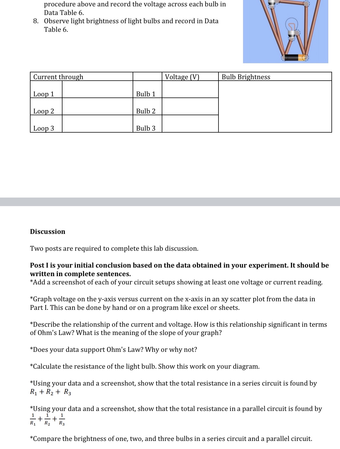
Build and understand the principles of a simple electric circuit*Verify Ohm's law for a known resistorLink:https://phet.colorado.edu/en/simulation/circuit-construction-kit-dc-virtual-labPart I: Ohm's LawObjectives:*Build and understand the principles of a simple electric circuit*Verify Ohm's law for a known resistorProcedure:Part A: Measuring CurrentYour first circuit will consist of a 1.5V battery and a 100-ohm resistor. You will use 2 wires to set up the circuit as shown in the illustration.1. To take the ammeter reading, drag the crosshair onto either of the wires and record the reading in Data Table 1.2. Change the voltage of the battery to 3.0 V and record the current reading.3. Repeat at least 5 more times with varying battery voltage.Data Table 1Measured Current (A) Measured Voltage across battery (V)Measured Voltage across resistor (V)1.5V 3.0V 4. Use an x-y scatter graph to graph voltage across the resistor on the y-axis versus current on the x-axis.Part B: Measuring Voltage1. Drag the voltmeter onto the screen. 2. Set up the voltmeter by adding it in parallel to and outside of the main circuit. 3. Attach the voltmeter's positive red lead to the positive end of the battery and attachthe voltmeter's negative black lead to the negative end of the battery. 4. Take the voltage reading and record in the data table.5. Reverse the DMM leads at points on either side of the batteries. Observe and explain your observation.6. Reposition the voltmeter to take a voltage reading on either side of the resistor, first with the leads in one position and then with the leads reversed. 7. Repeat with the same voltages as used in Part A. Record in the data table8. Be prepared to explain these voltage readings.Part II: Resistors in Series and ParallelObjectives:*Learn how resistors are used in series and in parallel*Construct electrical circuits in series and in parallel*Visually observe the difference in light intensity between light bulbs in series and in parallelProcedure:Part A: Resistors in Series1. Build a series circuit as shown by using a battery, one light bulb, and two wires.2. Record the current reading into Data Table 2. 3. Observe the light brightness (intensity) of the light bulb and record in Data Table 2. 4. Measure the voltage across the light bulb using the voltmeter.5. Use Ohm's law to calculate the closed circuit (hot) bulb resistance and record in Data Table 2.Data Table 2Current (mA) Voltage (V) Calculated Resistance (?)Bulb BrightnessSingle Bulb6. Build another circuit by adding two light bulbs in series. Using the same volt and ohm settings.7. Record current reading and voltage reading at points A, B, and C into Data Table 3.8. Observe light brightness (intensity) of light bulbs and record in Data Table 3.9. Use Ohm's law to calculate the closed circuit (hot) bulb resistance and record in Data Table 3.Data Table 3 Two Bulb SeriesCurrent (mA)Voltage (V) Calculated Resistance (?)Bulb BrightnessABC10. Build another circuit by adding three light bulbs in series. Using the same volt and ohm settings.11. Record current reading and voltage reading at points A, B, and C into Data Table 4.12. Observe light brightness (intensity) of light bulbs and record in Data Table 4.Data Table 4Current Voltage (V) Bulb BrightnessABCDPart B: Resistors in Parallel1. Build another circuit as shown by using two light bulbs connected in parallel. 2. Record current reading through Loop1 and Loop 2 into Data Table 5.3. Measure voltage across each light bulb as done in the one bulb procedure above and record the voltage across each bulb in Data Table 5.4. Observe light brightness of light bulbs and record in Data Table 5.Current through Voltage (V) Bulb BrightnessLoop 1 Bulb 1Loop 2 Bulb 25. Build another circuit as shown by using three light bulbs connected in parallel. 6. Record current reading through Loop1 and Loop 2 into Data Table 6.7. Measure voltage across each light bulb as done in the one bulb procedure above and record the voltage across each bulb in Data Table 6.8. Observe light brightness of light bulbs and record in Data Table 6.Current through Voltage (V) Bulb BrightnessLoop 1 Bulb 1Loop 2 Bulb 2Loop 3 Bulb 3

Step by Step Solution
There are 3 Steps involved in it
Step: 1

Get Instant Access to Expert-Tailored Solutions
See step-by-step solutions with expert insights and AI powered tools for academic success
Step: 2

Step: 3

Ace Your Homework with AI
Get the answers you need in no time with our AI-driven, step-by-step assistance
Get Started


