Answered step by step
Verified Expert Solution
Question
1 Approved Answer
C++ Your team is asked to design a water pump control system as shown on figure 1. In this system, the power switch is connected
C++

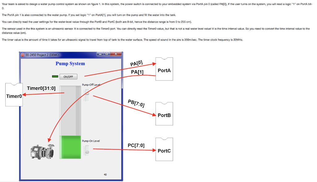
Your team is asked to design a water pump control system as shown on figure 1. In this system, the power switch is connected to your embedded system via PortA pin O (called PAIOD, If the user turns on the system, you will read a logic 1 on PortA bit- 0. The PortA pin 1 is also connected to the water pump. If you set logic 1" on PortAl1], you will turn on the pump and fill the water into the tank You can directly read the user settings for the water-level value through the PortB and PortC (both are 8-bit, hence the distance range is from 0 to 255 cm). The sensor used in the this system is an ultrasonic sensor. It is connected to the Timero port. You can directly read the TimerO value, but that is not a real water level valua! it is the time interval value. So you need to convert the time interval value to the distance value (cm) The timer value is the amount of time it takes for an ultrasonic signal to travel from top of tank to the water surface. The speed of sound in the airs is 350m/sec. The timer clock frequency is 20MHz. EE-2450 Project 2 (DEMO PAIO] PA1] PortA Pump System ? ONOFF Pump-off L Timer0[31:0] Timero PBI7:0] PortB Pump-On Level PC[7:0] PortC 40
Step by Step Solution
There are 3 Steps involved in it
Step: 1

Get Instant Access to Expert-Tailored Solutions
See step-by-step solutions with expert insights and AI powered tools for academic success
Step: 2

Step: 3

Ace Your Homework with AI
Get the answers you need in no time with our AI-driven, step-by-step assistance
Get Started


