Answered step by step
Verified Expert Solution
Question
1 Approved Answer
CA W MI 110 V V FRL Figure 11-18. System for Exercise 11-26. 11-26. The pneumatic system of Fig. 11-18 contains a double-rod cylinder controlled
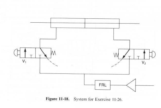
CA W MI 110 V V FRL Figure 11-18. System for Exercise 11-26. 11-26. The pneumatic system of Fig. 11-18 contains a double-rod cylinder controlled by two three-way, two-position, directional control valves. Describe the four operat- ing conditions for this system. 11-27. For the system of Exercise 11-26, as shown in Fig. 11-18, the cylinder is free (both ends vented to the atmosphere) in the unactuated (spring offset) position of the directional control valves. Redesign the system using the same components to accomplish the following operations: a. The cylinder rod moves left when only VI is actuated. b. The cylinder rod moves right when only V2 is actuated. c. The cylinder rod stops moving when a single actuated valve is unactuated (both valves are unactuated). d. When both valves are actuated, the cylinder is free (both ends are vented to the atmosphere)
Step by Step Solution
There are 3 Steps involved in it
Step: 1
Get Instant Access to Expert-Tailored Solutions
See step-by-step solutions with expert insights and AI powered tools for academic success
Step: 2
Step: 3
Ace Your Homework with AI
Get the answers you need in no time with our AI-driven, step-by-step assistance
Get Started