Question: can someone help me with those questions ? I really need it. Thank you ! The 4-bit register (R) employed in the following logic circuit

can someone help me with those questions ?
I really need it. Thank you !
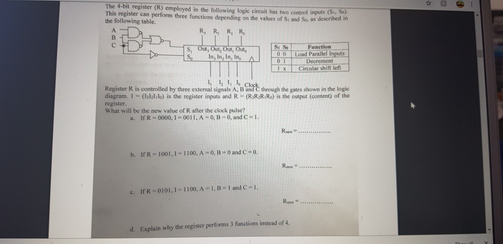
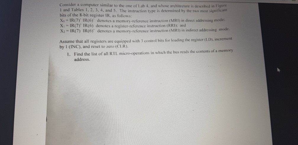
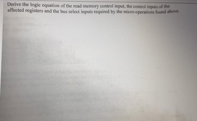
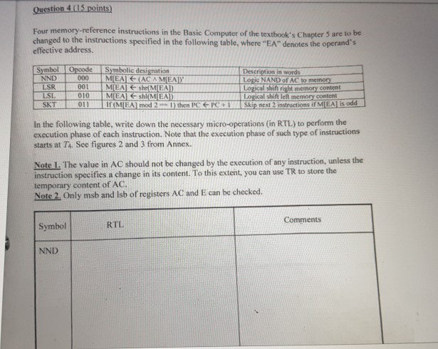
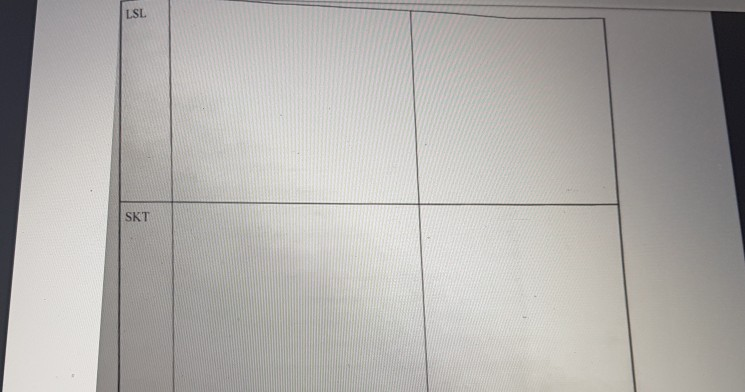
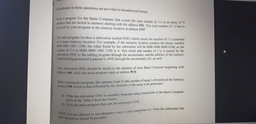
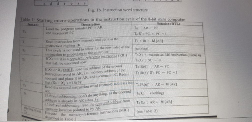
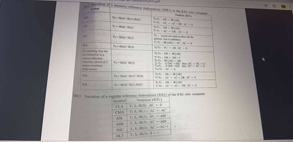
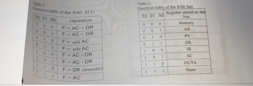
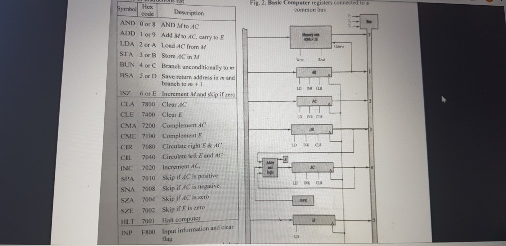
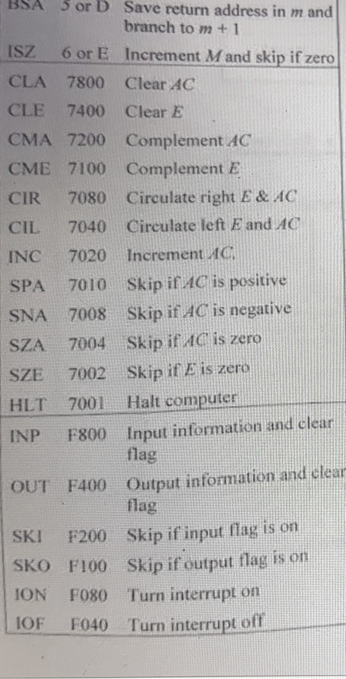
The 4-bit register (R) employed in the following logic circuit has two control inputs (SISON This register can perform three functions depending on the values of Su and So, as described the following table. R RR, R. R- C Si Se Function S Out, Out, Out, Out, 00 Load Parallel Inputs In, In, In, In, A 01 Decrement 1x Circular shift left 11,11 Clock Register R is controlled by three external signals A, B and C through the gates shown in the logic diagram. I = (blall) is the register inputs and R = (R:RR Ro) is the output (content) of the register. What will be the new value of R after the clock pulse? a. IfR=0000, 1 = 0011, A=0, B = 0, and C=1 b. IfR=1001.1 - 1100, A-0, B -0 and C -0. c. IfR = 0101.1 - 1100. A - 1. B = 1 and C -1. d. Explain why the register performs 3 functions instead of 4. Consider a computer similar to the one of Lab 4. and whose architecture is described in Figure 1 and Tables 1. 2. 3. 4. and 5. The instruction type is determined by the two most significant bits of the 8-bit register IR. as follows: Xo - IR(7) TR(6) denotes a memory-reference instruction (MRI) in direct addressing mode X1 = IR(7) IR(6) denotes a register-reference instruction (RRI): and X2 - IR(7) IR(6) denotes a memory-reference instruction (MRI)in indirect addressing mode. Assume that all registers are equipped with 3 control bits for loading the register (LD), increment by 1 (INC), and reset to zero (CLR). 1. Find the list of all RTL micro-operations in which the bus reads the contents of a memory address. Derive the logic equation of the read memory control input, the control inputs of the affected registers and the bus select inputs required by the micro-operations found above. Question 4 (15 points) Four memory-reference instructions in the Basic Computer of the textbook's Chapter 5 are to be changed to the instructions specified in the following table, where "EA" denotes the operand's effective address. Symbol NND ISR Opcode Symbolic designation 000M EA (ACA MEATY 001 MEA shr(MEA) 010 MEA shl(MEA) 011 IF(MEAmod 2-1) then PC Description in words Loric NAND of AC to memory Logical shih right memory content Logical shift left memory content Skip next 2 instructions if M EAJ is odd PC + In the following table, write down the necessary micro-operations (in RTL) to perform the execution phase of each instruction. Note that the execution phase of such type of instructions starts at T4. See figures 2 and 3 from Annex. Note I. The value in AC should not be changed by the execution of any instruction, unless the instruction specifies a change in its content. To this extent, you can use TR to store the temporary content of AC. Note 2. Only msb and Isb of registers AC and E can be checked. Comments Symbol RTL NND LSR LSL dresses in these questions are provided in hexadecimal format. Write a program for the Basic Computer that counts the total number of I's in an array of N mbers that are stored in memory starting with the address F01. This total number of l's has to he stored by your program in the memory location at address EFF. The main program invokes a subroutine (called ONE) which counts the number of l's contained in a single memory location. For example, if the memory location contains the binary number 0000 0000 1001 1100, the value found by the subroutine will be 0000 0000 0000 0100, as the number of l's in 0000 0000 1001 1100 is 4. This result (the number of I's) is passed by the subroutine ONE to the calling program through the accumulator, and the address of the memory location being processed is passed to ONE through the accumulator AC, as well. Your subroutine ONE should be stored in the memory of your Basic Computer beginning with address A00, while the main program starts at address 9C0. Delore running the program, the operator loads N (the number of array's elements) at the memory location Foo which is then followed by the elements of the array to be processed. 4) Write the subroutine ONE in assembly language using instructions of the Basic Computer given in the Table 6 from the Annex; Write the main program that calls the subroutine ONE. NOTE: You are allow ou are allowed to use alternative ways to pass parameters to/from the subroutine, but explanations should be provided. address Fig. Ib. Instruction word structure able l: Starting micro-operations in the instruction cycle of the 8-bit mini computer Instant Description Notation (RTL) Load the program counter PC in AR To AR - PC and increment PC To SPC - PC +1 Read instruction from memory and put it in the T:: IR - MTARI instruction register IR This cycle is not used to allow for the new value of the nothing) instruction to propagate in the controller 1 TX execute an RRI instruction (Table 4) IX it is a register - reference instruction (RRI) that will be executed now TsX SC-0 TSIR(6) AR - PC Xoor X2 (MRI) load the address of the second construction word to AR. ic. memory address of the TSTR(6) S: PC - PC operand and place it in AR. and increment PC Recall that Xo - X ) =TR(6) Read the second instruction word (memory T AIR(6) AR - MIAR] AR ing, as the operand direct addressing, don't do anything T. Xo: (nothing) dress is already in AR since 74 Berand address from TsX : R - MARI indirect addressing, read the operare Somory location pointed to by AK structions (MRI) cute the memory-reference instruct (see Table 2) Executo " described in Table 2 Symbol LUUT NU-Solutions%20(1).pdf Execution of a memory-reference instructions (MRI) in the 8-bit mini computer Natation (RTL) Yo-IR(6) IR(1) TROY Ts Yo : DR - MARI T: Yo : AC - AC-DR.SC- Y1 = IR(6)* IR(2) ToY: DR - MART TiY: : AC - DR.SC - To: (cycle not used to allow for the Y21R(6)' IR(3) address bus to stabilize) T: Y: MARI - AC.SC - Y3 IR(6)' IR(4) To Y : PC - AR.SC-O ISZ (assuming that the ToY: DR - MAR] test instruction is a TY4 : DR-DR+1 memory-reference TAYMIAR) - DR instruction, stored at 2 Y 4-IR(6) TR(5) To Y : DR = 0;S' then (PC - PC +1) TIDYA ! if (DROS hen PC PC +1 memory locations T10 Y : SC -0 further down) To YS : DR MARJ AND Ys --IR(6) IRL) IRO) TY: AC - AC A DR.SCO To Yo: DR --MIARI SUB Ye=1R(6) IR(1) IRO) TY: AC - AC - DR.SC-O labe 3: Execution of a register-reference instructions (RRI) of the 8-bit mini computer Symbol Notation (RTL) CLA TXIR(O): AC 0 CMA T, X, IR(1): AC - AC ASL Ty XIR(2): AC - ashl ASR | T, X, IR(3): AC - ashr INC T, X, IR(4): AC-AC+ HLT TX, IR(5) S-1 Table 4 S2 S1 So Function table of the 8-bit AL Operation 0 AC DR FAC - DR F sh Ac Fashr AC FAC DR FAC DRI 0 F DR (transfe IF - AC Table 5 Function table of the 8-bit bus S2 S So Register placed on the bus Memory AR PC 11 DR IR AC OUTA None ULLICIS LIST od Fig. 2. Basic Computer registers connected to a common bus Description Watu 005X16 LD NR CLR DNR CR Symbol AND O or 8 AND M to AC ADD I or 9 Add Mto AC, carry to E LDA 2 or A Load AC from M STA 3 or B Store AC in M BUN 4 or C Branch unconditionally to m BSA 5 or D Save return address in mand branch to m+ 1 ISZ 6 or E Increment M and skip if zero CLA 7800 Clear 4C CLE 7400 Clear E CMA 7200 Complement AC CME 7100 Complement E CIR 7080 Circulate right E& AC CIL 7040 Circulate left E and AC INC 7020 Increment AC SPA 7010 Skip if AC is positive SNA 7008 Skip if AC is negative SZA 7004 Skip if AC is zero SZE 7002 Skip if Eis zero HLT 7001 Halt computer INP F800 Input information and clear flag BSA 5 or D Save return address in m and branch to m + 1 ISZ 6 or E Increment Mand skip if zero CLA 7800 Clear AC CLE 7400 Clear E CMA 7200 Complement AC CME 7100 Complement E CIR 7080 Circulate right E & AC) CIL 7040 Circulate left E and AC INC 7020 Increment AC SPA 2010 Skip iC AC is positive SNA 7008 Skip if AC is negative SZA 7004 Skip if AC' is zero SZE 7002 Skip if I is zero HLT 7001 Halt computer INP F800 Input infermation and clear OUT F400 Output information and clear flag SKI F200 Skip if input flag is on SKO F100 Skip if output flag is on ION FO80 Turn interrupt on 1OF F040 Turn interrupt ofl The 4-bit register (R) employed in the following logic circuit has two control inputs (SISON This register can perform three functions depending on the values of Su and So, as described the following table. R RR, R. R- C Si Se Function S Out, Out, Out, Out, 00 Load Parallel Inputs In, In, In, In, A 01 Decrement 1x Circular shift left 11,11 Clock Register R is controlled by three external signals A, B and C through the gates shown in the logic diagram. I = (blall) is the register inputs and R = (R:RR Ro) is the output (content) of the register. What will be the new value of R after the clock pulse? a. IfR=0000, 1 = 0011, A=0, B = 0, and C=1 b. IfR=1001.1 - 1100, A-0, B -0 and C -0. c. IfR = 0101.1 - 1100. A - 1. B = 1 and C -1. d. Explain why the register performs 3 functions instead of 4. Consider a computer similar to the one of Lab 4. and whose architecture is described in Figure 1 and Tables 1. 2. 3. 4. and 5. The instruction type is determined by the two most significant bits of the 8-bit register IR. as follows: Xo - IR(7) TR(6) denotes a memory-reference instruction (MRI) in direct addressing mode X1 = IR(7) IR(6) denotes a register-reference instruction (RRI): and X2 - IR(7) IR(6) denotes a memory-reference instruction (MRI)in indirect addressing mode. Assume that all registers are equipped with 3 control bits for loading the register (LD), increment by 1 (INC), and reset to zero (CLR). 1. Find the list of all RTL micro-operations in which the bus reads the contents of a memory address. Derive the logic equation of the read memory control input, the control inputs of the affected registers and the bus select inputs required by the micro-operations found above. Question 4 (15 points) Four memory-reference instructions in the Basic Computer of the textbook's Chapter 5 are to be changed to the instructions specified in the following table, where "EA" denotes the operand's effective address. Symbol NND ISR Opcode Symbolic designation 000M EA (ACA MEATY 001 MEA shr(MEA) 010 MEA shl(MEA) 011 IF(MEAmod 2-1) then PC Description in words Loric NAND of AC to memory Logical shih right memory content Logical shift left memory content Skip next 2 instructions if M EAJ is odd PC + In the following table, write down the necessary micro-operations (in RTL) to perform the execution phase of each instruction. Note that the execution phase of such type of instructions starts at T4. See figures 2 and 3 from Annex. Note I. The value in AC should not be changed by the execution of any instruction, unless the instruction specifies a change in its content. To this extent, you can use TR to store the temporary content of AC. Note 2. Only msb and Isb of registers AC and E can be checked. Comments Symbol RTL NND LSR LSL dresses in these questions are provided in hexadecimal format. Write a program for the Basic Computer that counts the total number of I's in an array of N mbers that are stored in memory starting with the address F01. This total number of l's has to he stored by your program in the memory location at address EFF. The main program invokes a subroutine (called ONE) which counts the number of l's contained in a single memory location. For example, if the memory location contains the binary number 0000 0000 1001 1100, the value found by the subroutine will be 0000 0000 0000 0100, as the number of l's in 0000 0000 1001 1100 is 4. This result (the number of I's) is passed by the subroutine ONE to the calling program through the accumulator, and the address of the memory location being processed is passed to ONE through the accumulator AC, as well. Your subroutine ONE should be stored in the memory of your Basic Computer beginning with address A00, while the main program starts at address 9C0. Delore running the program, the operator loads N (the number of array's elements) at the memory location Foo which is then followed by the elements of the array to be processed. 4) Write the subroutine ONE in assembly language using instructions of the Basic Computer given in the Table 6 from the Annex; Write the main program that calls the subroutine ONE. NOTE: You are allow ou are allowed to use alternative ways to pass parameters to/from the subroutine, but explanations should be provided. address Fig. Ib. Instruction word structure able l: Starting micro-operations in the instruction cycle of the 8-bit mini computer Instant Description Notation (RTL) Load the program counter PC in AR To AR - PC and increment PC To SPC - PC +1 Read instruction from memory and put it in the T:: IR - MTARI instruction register IR This cycle is not used to allow for the new value of the nothing) instruction to propagate in the controller 1 TX execute an RRI instruction (Table 4) IX it is a register - reference instruction (RRI) that will be executed now TsX SC-0 TSIR(6) AR - PC Xoor X2 (MRI) load the address of the second construction word to AR. ic. memory address of the TSTR(6) S: PC - PC operand and place it in AR. and increment PC Recall that Xo - X ) =TR(6) Read the second instruction word (memory T AIR(6) AR - MIAR] AR ing, as the operand direct addressing, don't do anything T. Xo: (nothing) dress is already in AR since 74 Berand address from TsX : R - MARI indirect addressing, read the operare Somory location pointed to by AK structions (MRI) cute the memory-reference instruct (see Table 2) Executo " described in Table 2 Symbol LUUT NU-Solutions%20(1).pdf Execution of a memory-reference instructions (MRI) in the 8-bit mini computer Natation (RTL) Yo-IR(6) IR(1) TROY Ts Yo : DR - MARI T: Yo : AC - AC-DR.SC- Y1 = IR(6)* IR(2) ToY: DR - MART TiY: : AC - DR.SC - To: (cycle not used to allow for the Y21R(6)' IR(3) address bus to stabilize) T: Y: MARI - AC.SC - Y3 IR(6)' IR(4) To Y : PC - AR.SC-O ISZ (assuming that the ToY: DR - MAR] test instruction is a TY4 : DR-DR+1 memory-reference TAYMIAR) - DR instruction, stored at 2 Y 4-IR(6) TR(5) To Y : DR = 0;S' then (PC - PC +1) TIDYA ! if (DROS hen PC PC +1 memory locations T10 Y : SC -0 further down) To YS : DR MARJ AND Ys --IR(6) IRL) IRO) TY: AC - AC A DR.SCO To Yo: DR --MIARI SUB Ye=1R(6) IR(1) IRO) TY: AC - AC - DR.SC-O labe 3: Execution of a register-reference instructions (RRI) of the 8-bit mini computer Symbol Notation (RTL) CLA TXIR(O): AC 0 CMA T, X, IR(1): AC - AC ASL Ty XIR(2): AC - ashl ASR | T, X, IR(3): AC - ashr INC T, X, IR(4): AC-AC+ HLT TX, IR(5) S-1 Table 4 S2 S1 So Function table of the 8-bit AL Operation 0 AC DR FAC - DR F sh Ac Fashr AC FAC DR FAC DRI 0 F DR (transfe IF - AC Table 5 Function table of the 8-bit bus S2 S So Register placed on the bus Memory AR PC 11 DR IR AC OUTA None ULLICIS LIST od Fig. 2. Basic Computer registers connected to a common bus Description Watu 005X16 LD NR CLR DNR CR Symbol AND O or 8 AND M to AC ADD I or 9 Add Mto AC, carry to E LDA 2 or A Load AC from M STA 3 or B Store AC in M BUN 4 or C Branch unconditionally to m BSA 5 or D Save return address in mand branch to m+ 1 ISZ 6 or E Increment M and skip if zero CLA 7800 Clear 4C CLE 7400 Clear E CMA 7200 Complement AC CME 7100 Complement E CIR 7080 Circulate right E& AC CIL 7040 Circulate left E and AC INC 7020 Increment AC SPA 7010 Skip if AC is positive SNA 7008 Skip if AC is negative SZA 7004 Skip if AC is zero SZE 7002 Skip if Eis zero HLT 7001 Halt computer INP F800 Input information and clear flag BSA 5 or D Save return address in m and branch to m + 1 ISZ 6 or E Increment Mand skip if zero CLA 7800 Clear AC CLE 7400 Clear E CMA 7200 Complement AC CME 7100 Complement E CIR 7080 Circulate right E & AC) CIL 7040 Circulate left E and AC INC 7020 Increment AC SPA 2010 Skip iC AC is positive SNA 7008 Skip if AC is negative SZA 7004 Skip if AC' is zero SZE 7002 Skip if I is zero HLT 7001 Halt computer INP F800 Input infermation and clear OUT F400 Output information and clear flag SKI F200 Skip if input flag is on SKO F100 Skip if output flag is on ION FO80 Turn interrupt on 1OF F040 Turn interrupt ofl
Step by Step Solution
There are 3 Steps involved in it

Get step-by-step solutions from verified subject matter experts


