

Question: Case 1. Methanol Synthesis Process B-6 Chlorine FT Water Reactor Mixing coil LO To bottles 50% NaOH Dilute NaOH Bleach Figure B-9 Ratio control to
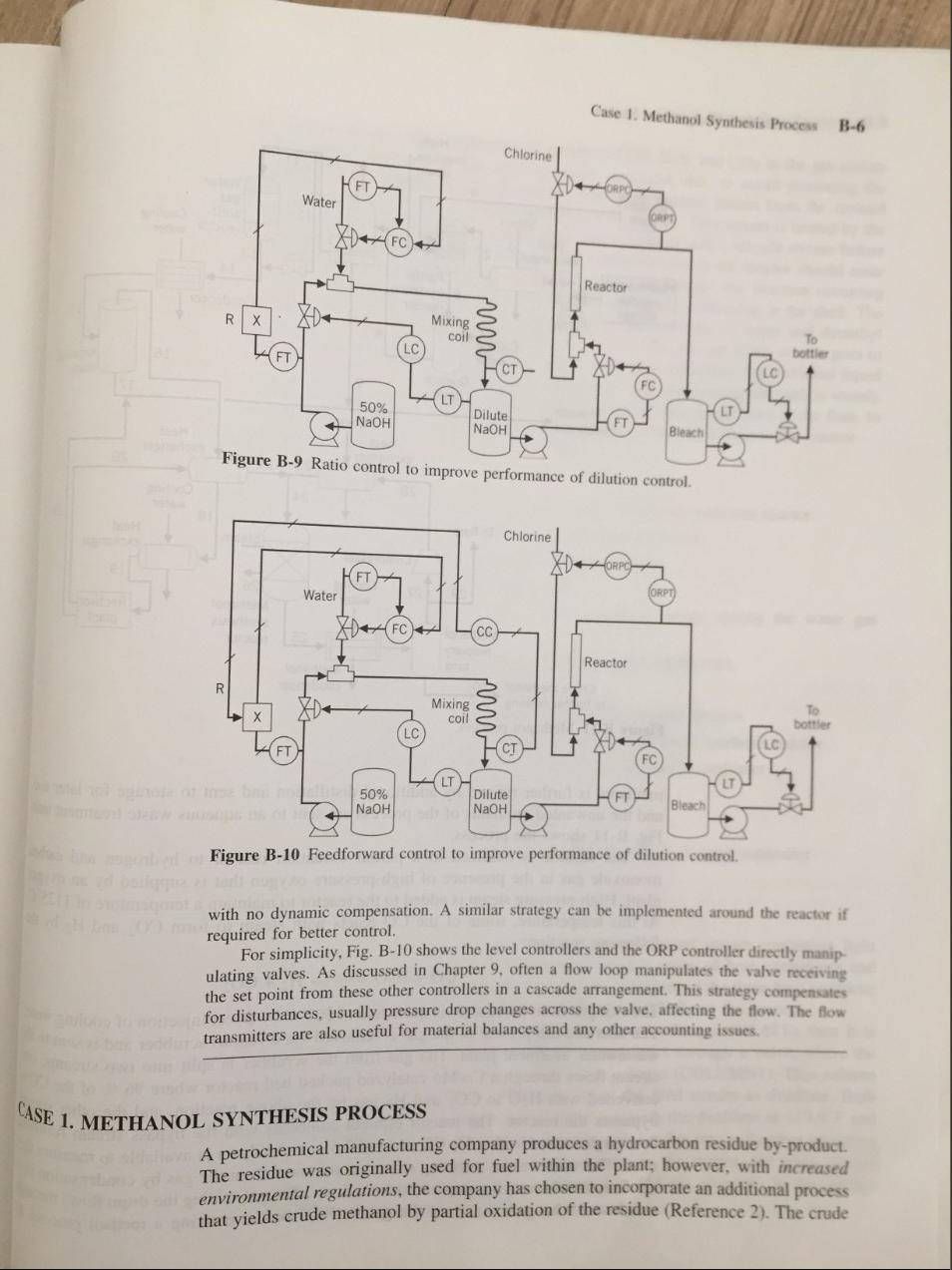
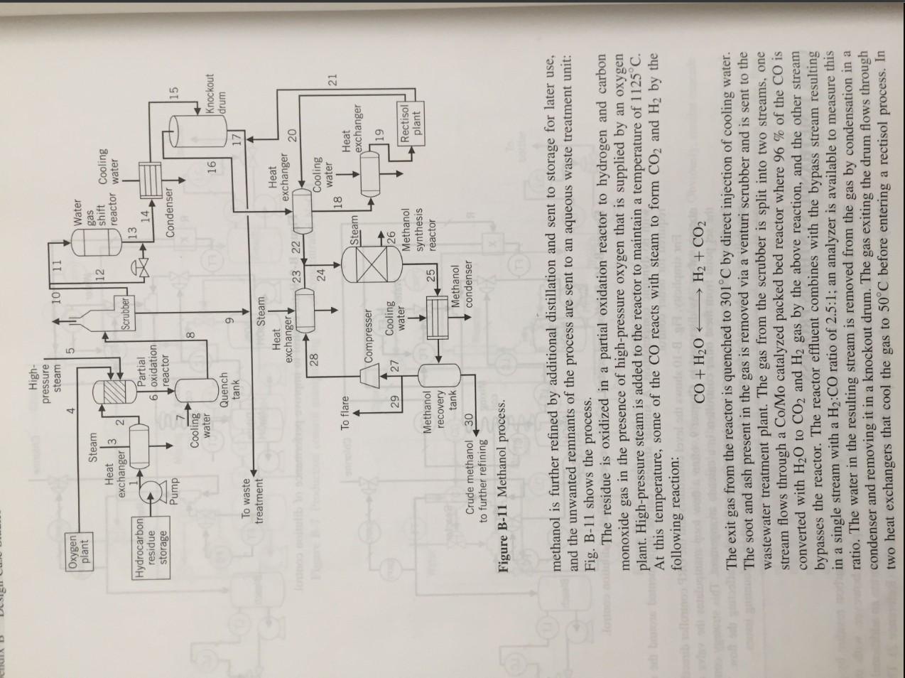
Case 1. Methanol Synthesis Process B-6 Chlorine FT Water Reactor Mixing coil LO To bottles 50% NaOH Dilute NaOH Bleach Figure B-9 Ratio control to improve performance of dilution control Chlorine FT Water FC) Reactor R Mixing coil To botter LC 50% NaOH Dilute NaOH Bleach Figure B-10 Feedforward control to improve performance of dilution control. with no dynamic compensation. A similar strategy can be implemented around the reactor if required for better control. For simplicity, Fig. B-10 shows the level controllers and the ORP controller directly manip ulating valves. As discussed in Chapter 9. often a flow loop manipulates the valve receiving the set point from these other controllers in a cascade arrangement. This strategy compensates for disturbances, usually pressure drop changes across the valve, affecting the flow. The flow transmitters are also useful for material balances and any other accounting issues. CASE 1. METHANOL SYNTHESIS PROCESS A petrochemical manufacturing company produces a hydrocarbon residue by-product. The residue was originally used for fuel within the plant; however, with increased environmental regulations, the company has chosen to incorporate an additional process that yields crude methanol by partial oxidation of the residue (Reference 2). The crude High- pressure steam 4 10 11 5 Oxygen plant 12 12 Steam Heat exchanger Water gas shift Cooling reactor water 13 14 Scrubber Hydrocarbon residue H Partial 6 oxidation reactor storage Condenser Pump 15 8 Cooling water Quench tank 161 Knockout drum 9 17 To waste treatment Steam Heat exchanger Heat exchanger 23 22 20 28 24 Cooling water 18 Heat exchanger 21 To flare Steam Compresser 19 29 27 Cooling water 126 Methanol synthesis reactor Rectisol plant 25 Methanol recovery tank Crude methanol 30 to further refining Figure B-11 Methanol process. Methanol condenser methanol is further refined by additional distillation and sent to storage for later use, and the unwanted remnants of the process are sent to an aqueous waste treatment unit: Fig. B-11 shows the process. The residue is oxidized in a partial oxidation reactor to hydrogen and carbon monoxide gas in the presence of high-pressure oxygen that is supplied by an oxygen plant. High-pressure steam is added to the reactor to maintain a temperature of 1125C. At this temperature, some of the CO reacts with steam to form CO2 and H2 by the following reaction: CO + H2O + H2 + CO2 The exit gas from the reactor is quenched to 301C by direct injection of cooling water. The soot and ash present in the gas is removed via a venturi scrubber and is sent to the wastewater treatment plant. The gas from the scrubber is split into two streams, one stream flows through a Co/Mo catalyzed packed bed reactor where 96 % of the CO is converted with H20 to CO2 and H2 gas by the above reaction, and the other stream bypasses the reactor. The reactor effluent combines with the bypass stream resulting in a single stream with a H2:CO ratio of 2.5:1; an analyzer is available to measure this ratio. The water in the resulting stream is removed from the gas by condensation in a condenser and removing it in a knockout drum. The gas exiting the drum flows through two heat exchangers that cool the gas to 50C before entering a rectisol process. In Case 2. Hydrocarbon Process B-8 the rectisol process the combustion by-products COS, H2S, and CO2 in the gas stream are removed, and sent to the aqueous waste treatment unit, to avoid poisoning the catalyst in the methanol synthesis reactor. The other product stream from the rectisol process contains CO, H2, and trace amounts of Ar and N2. This stream is heated by the exiting gas stream from the knockout drum and combined with a recycle stream before entering the methanol synthesis reactor. The combined feed to the reactor should enter at 200C. The synthesis reactor looks like a heat exchanger; the reaction occurring inside the tubes, which are filled with catalyst, and steam condensing in the shell. The H2 and CO gas is converted into methanol and trace amounts of water and dimethyl ether, the conversion of CO in the reactor is 12.7 %. The gas out of the reactor goes to a condenser to condense the methanol, and to a tank for separation; the methanol liquid goes to a distillation train for further purification. The gas leaving the tank is mainly unconverted H2 and CO with some Ar and N2. Part of this stream goes to the flare, to relieve the nonreactive gases, and the other portion is recycled back to the reactor. Design and draw the systems to control: A. Production rate. B. The temperature of the residue entering the partial oxidation reactor. C. The flow of O2 entering the partial oxidation reactor. D. The temperature in the partial oxidation reactor. E. The temperature in the quench tank. F. The H2:CO ratio of 2.5:1 in the combined stream exiting the water gas shift reactor. G. The temperature in the stream entering the knockout tank. H. The level in the knockout tank. I. The temperature of the stream entering the rectisol process. J. The temperature of the stream entering the methanol synthesis reactor. K. The temperature of the stream exiting the methanol condenser. L. The level in the methanol tank. M. The pressure in the methanol tank. Specify the fail-save action of every valve and the action of every controller. CASE 2. HYDROCARBON PROCESS A hydrocarbon processing plant purifies the incoming feed stream containing light hydrocarbons (two through six carbon chains) using a series of heat exchangers and distillation columns that capitalize on the relative volatilities of the three final products: propane, butane, and pentane (Reference 2). Figure B-12 shows the process. The feed to the process is first heated in a heat exchanger (HEAT1), then it is pumped to a second heat exchanger (HEAT2), and flows through a valve, where the pressure is reduced to 253 psi, into a distillation column (COLUMN1). This column is responsible for the separation of propane from the feed stream as distillate. Both liquid streams leaving the column are at 253.1 psi, with the distillate at 119.9F and the bottoms at 229.5F. The distillate flashes through a valve into a chamber operating at 100F and 196.5 psi, to purge the ethane present in the stream; the purge stream is a vapor. The residual liquid stream is pumped to 450 psi, resulting in the product stream at the temperature of 104.7F. Case 1. Methanol Synthesis Process B-6 Chlorine FT Water Reactor Mixing coil LO To bottles 50% NaOH Dilute NaOH Bleach Figure B-9 Ratio control to improve performance of dilution control Chlorine FT Water FC) Reactor R Mixing coil To botter LC 50% NaOH Dilute NaOH Bleach Figure B-10 Feedforward control to improve performance of dilution control. with no dynamic compensation. A similar strategy can be implemented around the reactor if required for better control. For simplicity, Fig. B-10 shows the level controllers and the ORP controller directly manip ulating valves. As discussed in Chapter 9. often a flow loop manipulates the valve receiving the set point from these other controllers in a cascade arrangement. This strategy compensates for disturbances, usually pressure drop changes across the valve, affecting the flow. The flow transmitters are also useful for material balances and any other accounting issues. CASE 1. METHANOL SYNTHESIS PROCESS A petrochemical manufacturing company produces a hydrocarbon residue by-product. The residue was originally used for fuel within the plant; however, with increased environmental regulations, the company has chosen to incorporate an additional process that yields crude methanol by partial oxidation of the residue (Reference 2). The crude High- pressure steam 4 10 11 5 Oxygen plant 12 12 Steam Heat exchanger Water gas shift Cooling reactor water 13 14 Scrubber Hydrocarbon residue H Partial 6 oxidation reactor storage Condenser Pump 15 8 Cooling water Quench tank 161 Knockout drum 9 17 To waste treatment Steam Heat exchanger Heat exchanger 23 22 20 28 24 Cooling water 18 Heat exchanger 21 To flare Steam Compresser 19 29 27 Cooling water 126 Methanol synthesis reactor Rectisol plant 25 Methanol recovery tank Crude methanol 30 to further refining Figure B-11 Methanol process. Methanol condenser methanol is further refined by additional distillation and sent to storage for later use, and the unwanted remnants of the process are sent to an aqueous waste treatment unit: Fig. B-11 shows the process. The residue is oxidized in a partial oxidation reactor to hydrogen and carbon monoxide gas in the presence of high-pressure oxygen that is supplied by an oxygen plant. High-pressure steam is added to the reactor to maintain a temperature of 1125C. At this temperature, some of the CO reacts with steam to form CO2 and H2 by the following reaction: CO + H2O + H2 + CO2 The exit gas from the reactor is quenched to 301C by direct injection of cooling water. The soot and ash present in the gas is removed via a venturi scrubber and is sent to the wastewater treatment plant. The gas from the scrubber is split into two streams, one stream flows through a Co/Mo catalyzed packed bed reactor where 96 % of the CO is converted with H20 to CO2 and H2 gas by the above reaction, and the other stream bypasses the reactor. The reactor effluent combines with the bypass stream resulting in a single stream with a H2:CO ratio of 2.5:1; an analyzer is available to measure this ratio. The water in the resulting stream is removed from the gas by condensation in a condenser and removing it in a knockout drum. The gas exiting the drum flows through two heat exchangers that cool the gas to 50C before entering a rectisol process. In Case 2. Hydrocarbon Process B-8 the rectisol process the combustion by-products COS, H2S, and CO2 in the gas stream are removed, and sent to the aqueous waste treatment unit, to avoid poisoning the catalyst in the methanol synthesis reactor. The other product stream from the rectisol process contains CO, H2, and trace amounts of Ar and N2. This stream is heated by the exiting gas stream from the knockout drum and combined with a recycle stream before entering the methanol synthesis reactor. The combined feed to the reactor should enter at 200C. The synthesis reactor looks like a heat exchanger; the reaction occurring inside the tubes, which are filled with catalyst, and steam condensing in the shell. The H2 and CO gas is converted into methanol and trace amounts of water and dimethyl ether, the conversion of CO in the reactor is 12.7 %. The gas out of the reactor goes to a condenser to condense the methanol, and to a tank for separation; the methanol liquid goes to a distillation train for further purification. The gas leaving the tank is mainly unconverted H2 and CO with some Ar and N2. Part of this stream goes to the flare, to relieve the nonreactive gases, and the other portion is recycled back to the reactor. Design and draw the systems to control: A. Production rate. B. The temperature of the residue entering the partial oxidation reactor. C. The flow of O2 entering the partial oxidation reactor. D. The temperature in the partial oxidation reactor. E. The temperature in the quench tank. F. The H2:CO ratio of 2.5:1 in the combined stream exiting the water gas shift reactor. G. The temperature in the stream entering the knockout tank. H. The level in the knockout tank. I. The temperature of the stream entering the rectisol process. J. The temperature of the stream entering the methanol synthesis reactor. K. The temperature of the stream exiting the methanol condenser. L. The level in the methanol tank. M. The pressure in the methanol tank. Specify the fail-save action of every valve and the action of every controller. CASE 2. HYDROCARBON PROCESS A hydrocarbon processing plant purifies the incoming feed stream containing light hydrocarbons (two through six carbon chains) using a series of heat exchangers and distillation columns that capitalize on the relative volatilities of the three final products: propane, butane, and pentane (Reference 2). Figure B-12 shows the process. The feed to the process is first heated in a heat exchanger (HEAT1), then it is pumped to a second heat exchanger (HEAT2), and flows through a valve, where the pressure is reduced to 253 psi, into a distillation column (COLUMN1). This column is responsible for the separation of propane from the feed stream as distillate. Both liquid streams leaving the column are at 253.1 psi, with the distillate at 119.9F and the bottoms at 229.5F. The distillate flashes through a valve into a chamber operating at 100F and 196.5 psi, to purge the ethane present in the stream; the purge stream is a vapor. The residual liquid stream is pumped to 450 psi, resulting in the product stream at the temperature of 104.7F
Step by Step Solution
There are 3 Steps involved in it

Get step-by-step solutions from verified subject matter experts