Answered step by step
Verified Expert Solution
Question
1 Approved Answer
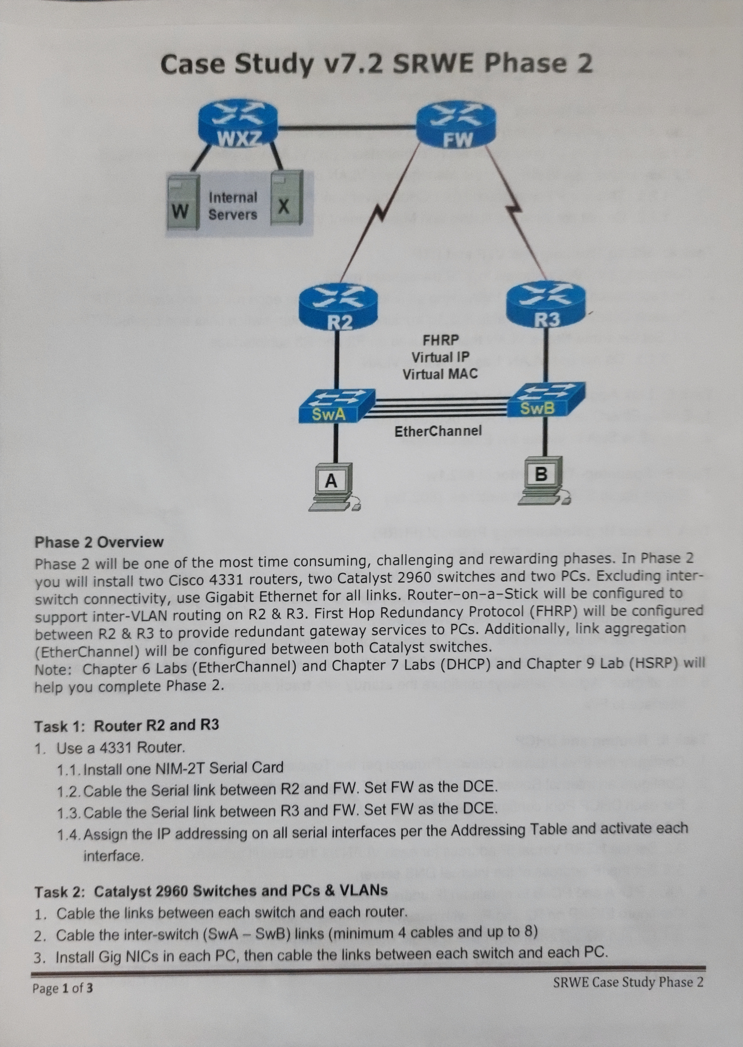
Case Study v7.2 SRWE Phase 2 K X FW W WXZ Internal Servers X K R2 S SWA A 2 FHRP Virtual IP Virtual


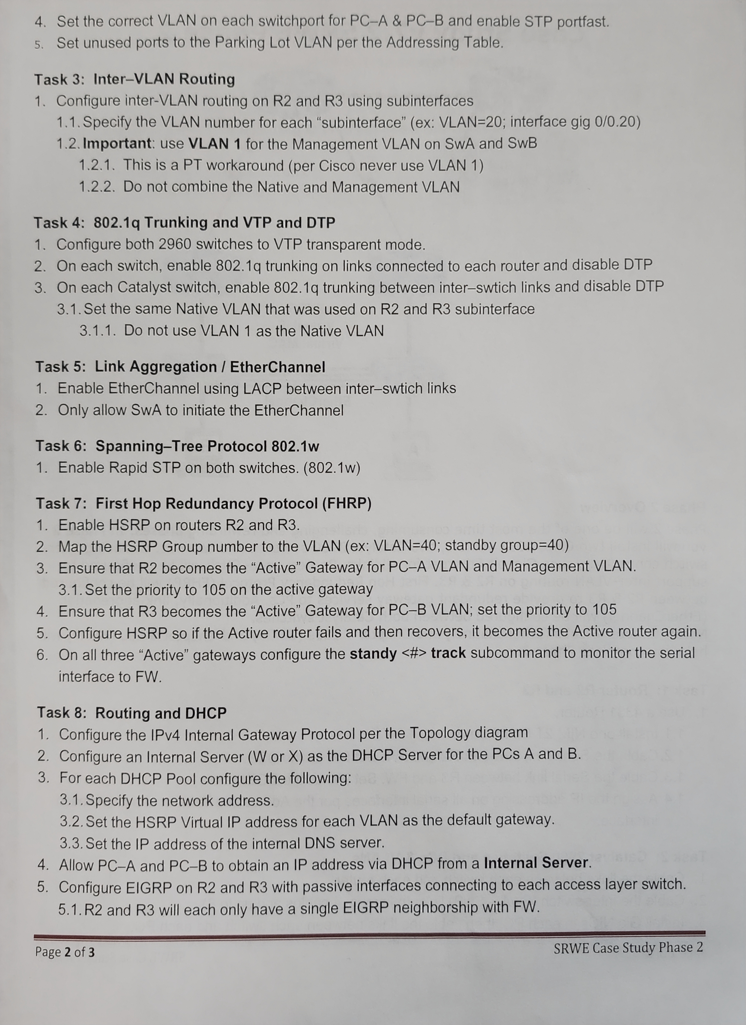
Case Study v7.2 SRWE Phase 2 K X FW W WXZ Internal Servers X K R2 S SWA A 2 FHRP Virtual IP Virtual MAC EtherChannel EX R3 Task 2: Catalyst 2960 Switches and PCs & VLANS 1. Cable the links between each switch and each router. SwB B Phase 2 Overview Phase 2 will be one of the most time consuming, challenging and rewarding phases. In Phase 2 you will install two Cisco 4331 routers, two Catalyst 2960 switches and two PCs. Excluding inter- switch connectivity, use Gigabit Ethernet for all links. Router-on-a-Stick will be configured to support inter-VLAN routing on R2 & R3. First Hop Redundancy Protocol (FHRP) will be configured between R2 & R3 to provide redundant gateway services to PCs. Additionally, link aggregation (EtherChannel) will be configured between both Catalyst switches. Note: Chapter 6 Labs (EtherChannel) and Chapter 7 Labs (DHCP) and Chapter 9 Lab (HSRP) will help you complete Phase 2. Task 1: Router R2 and R3 1. Use a 4331 Router. 1.1. Install one NIM-2T Serial Card 1.2. Cable the Serial link between R2 and FW. Set FW as the DCE. 1.3. Cable the Serial link between R3 and FW. Set FW as the DCE. 1.4. Assign the IP addressing on all serial interfaces per the Addressing Table and activate each interface. 2. Cable the inter-switch (SwA - SwB) links (minimum 4 cables and up to 8) 3. Install Gig NICs in each PC, then cable the links between each switch and each PC. Page 1 of 3 SRWE Case Study Phase 2 4. Set the correct VLAN on each switchport for PC-A & PC-B and enable STP portfast. 5. Set unused ports to the Parking Lot VLAN per the Addressing Table. Task 3: Inter-VLAN Routing 1. Configure inter-VLAN routing on R2 and R3 using subinterfaces 1.1. Specify the VLAN number for each "subinterface" (ex: VLAN=20; interface gig 0/0.20) 1.2. Important: use VLAN 1 for the Management VLAN on SwA and SwB 1.2.1. This is a PT workaround (per Cisco never use VLAN 1) 1.2.2. Do not combine the Native and Management VLAN Task 4: 802.1q Trunking and VTP and DTP 1. Configure both 2960 switches to VTP transparent mode. 2. On each switch, enable 802.1q trunking on links connected to each router and disable DTP 3. On each Catalyst switch, enable 802.1q trunking between inter-swtich links and disable DTP 3.1. Set the same Native VLAN that was used on R2 and R3 subinterface 3.1.1. Do not use VLAN 1 as the Native VLAN Task 5: Link Aggregation / EtherChannel 1. Enable EtherChannel using LACP between inter-swtich links 2. Only allow SwA to initiate the EtherChannel Task 6: Spanning-Tree Protocol 802.1w 1. Enable Rapid STP on both switches. (802.1w) Task 7: First Hop Redundancy Protocol (FHRP) 1. Enable HSRP on routers R2 and R3. 2. Map the HSRP Group number to the VLAN (ex: VLAN=40; standby group=40) 3. Ensure that R2 becomes the "Active" Gateway for PC-A VLAN and Management VLAN. 3.1. Set the priority to 105 on the active gateway 4. Ensure that R3 becomes the "Active" Gateway for PC-B VLAN; set the priority to 105 5. Configure HSRP so if the Active router fails and then recovers, it becomes the Active router again. 6. On all three "Active" gateways configure the standy track subcommand to monitor the serial interface to FW. Task 8: Routing and DHCP 1. Configure the IPv4 Internal Gateway Protocol per the Topology diagram 2. Configure an Internal Server (W or X) as the DHCP Server for the PCs A and B. 3. For each DHCP Pool configure the following: 3.1. Specify the network address. 3.2. Set the HSRP Virtual IP address for each VLAN as the default gateway. 3.3. Set the IP address of the internal DNS server. 4. Allow PC-A and PC-B to obtain an IP address via DHCP from a Internal Server. 5. Configure EIGRP on R2 and R3 with passive interfaces connecting to each access layer switch. 5.1. R2 and R3 will each only have a single EIGRP neighborship with FW. Page 2 of 3 SRWE Case Study Phase 2
Step by Step Solution
There are 3 Steps involved in it
Step: 1

Get Instant Access to Expert-Tailored Solutions
See step-by-step solutions with expert insights and AI powered tools for academic success
Step: 2

Step: 3

Ace Your Homework with AI
Get the answers you need in no time with our AI-driven, step-by-step assistance
Get Started


