

Question
Consider the actuation of 3 cylinders, A, B and C, with each cylinder controlled by a double solenoid activated 4/2 valve. Each cylinder will
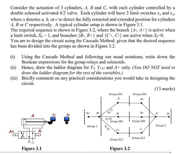
Consider the actuation of 3 cylinders, A, B and C, with each cylinder controlled by a double solenoid activated 4/2 valve. Each cylinder will have 2 limit switches x, and x, where x denotes a, b, or c to detect the fully retracted and extended position for cylinders A, B or C respectively. A typical cylinder setup is shown in Figure 3.1. The required sequence is shown in Figure 3.2, where the branch {A-, A+} is active when a limit switch, Xp = 1, and branches {B-, B+} and {C+, C-} are active when Xp=0. You are to design the circuit using the Cascade Method, given that the desired sequence has been divided into the groups as shown in Figure 3.2. (1) Using the Cascade Method and following our usual notations, write down the Boolean expressions for the group relays and solenoids. (ii) Hence, draw the ladder diagram for Y, Y242 and A+ only. (You DO NOT need to draw the ladder diagram for the rest of the variables.) (iii) Briefly comment on any practical considerations you would take in designing the circuit. (13 marks) A+ A A- XI Figure 3.1 a 32 B+ Group 1 Group 2A1 A- X=1 X=0 0=x B- Group 281 C+ Group 2A2 A+ Group 2C1 Figure 3.2 B+ 1 Group 282 Group 2C2 Group 3 Consider the actuation of 3 cylinders, A, B and C, with each cylinder controlled by a double solenoid activated 4/2 valve. Each cylinder will have 2 limit switches x, and x, where x denotes a, b, or c to detect the fully retracted and extended position for cylinders A, B or C respectively. A typical cylinder setup is shown in Figure 3.1. The required sequence is shown in Figure 3.2, where the branch {A-, A+} is active when a limit switch, X = 1, and branches {B-, B+} and {C+, C-} are active when Xp=0. You are to design the circuit using the Cascade Method, given that the desired sequence has been divided into the groups as shown in Figure 3.2. (1) Using the Cascade Method and following our usual notations, write down the Boolean expressions for the group relays and solenoids. (ii) Hence, draw the ladder diagram for Y, Y242 and A+ only. (You DO NOT need to draw the ladder diagram for the rest of the variables.) (iii) Briefly comment on any practical considerations you would take in designing the circuit. (13 marks) A+ A A- XI Figure 3.1 a 32 B+ Group 1 Group 2A1 A- X=1 X=0 0=x B- Group 281 C+ Group 2A2 A+ Group 2C1 Figure 3.2 B+ 1 Group 282 Group 2C2 Group 3
Step by Step Solution
There are 3 Steps involved in it
Step: 1

Get Instant Access with AI-Powered Solutions
See step-by-step solutions with expert insights and AI powered tools for academic success
Step: 2

Step: 3
Ace Your Homework with AI
Get the answers you need in no time with our AI-driven, step-by-step assistance
Get Started
Income Tax Fundamentals 2013
Authors: Gerald E. Whittenburg, Martha Altus Buller, Steven L Gill
31st Edition
1111972516, 978-1285586618, 1285586611, 978-1285613109, 978-1111972516