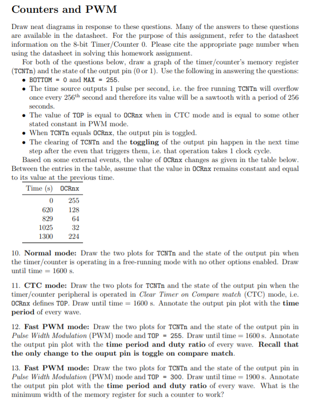
Counters and PWM Draw neat diagrams in response to these questions. Many of the answers to these questions are available in the datasheet. For the purpose of this assignment, refer to the datasheet information on the 8-bit Timer/Counter 0. Please cite the appropriate page number when using the datasheet in solving this homework assignment. For both of the questions below, draw a graph of the timer/counter's memory register (TCNTn) and the state of the output pin (0 or 1). Use the following in answering the questions: BOTTOM = 0 and MAX = 255. The time source outputs 1 pulse per second, i.e. the free running TCNTn will overflow once every 256th second and therefore its value will be a sawtooth with a period of 256 seconds. The value of TOP is equal to OCRnx when in CTC mode and is equal to some other stated constant in PWM mode. When TCNTn equals OCRnx, the output pin is toggled. The clearing of TCNTn and the toggling of the output pin happen in the next time step after the even that triggers them, i.e. that operation takes 1 clock cycle. Based on some external events, the value of OCRnx changes as given in the table below. Between the entries in the table, assume that the value in OCRnx remains constant and equal to its value at the previous time. Time (s) OCRnx 255 620 128 829 64 1025 1300224 32 10. Normal mode: Draw the two plots for TCNTn and the state of the output pin when the timer/counter is operating in a free-running mode with no other options enabled. Draw until time = 1600 s. 11. CTC mode: Draw the two plots for TCNTn and the state of the output pin when the timer/counter peripheral is operated in Clear Timer on Compare match (CTC) mode, i.e. OCRnx defines TOP. Draw until time = 1600 s. Annotate the output pin plot with the time period of every wave. 12. Fast PWM mode: Draw the two plots for TCNTn and the state of the output pin in Pulse Width Modulation (PWM) mode and TOP = 255. Draw until time = 1600 s. Annotate the output pin plot with the time period and duty ratio of every wave. Recall that the only change to the ouput pin is toggle on compare match. 13. Fast PWM mode: Draw the two plots for TCNTn and the state of the output pin in Pulse Width Modulation (PWM) mode and TOP = 300. Draw until time = 1900 s. Annotate the output pin plot with the time period and duty ratio of every wave. What is the minimum width of the memory register for such a counter to work? Counters and PWM Draw neat diagrams in response to these questions. Many of the answers to these questions are available in the datasheet. For the purpose of this assignment, refer to the datasheet information on the 8-bit Timer/Counter 0. Please cite the appropriate page number when using the datasheet in solving this homework assignment. For both of the questions below, draw a graph of the timer/counter's memory register (TCNTn) and the state of the output pin (0 or 1). Use the following in answering the questions: BOTTOM = 0 and MAX = 255. The time source outputs 1 pulse per second, i.e. the free running TCNTn will overflow once every 256th second and therefore its value will be a sawtooth with a period of 256 seconds. The value of TOP is equal to OCRnx when in CTC mode and is equal to some other stated constant in PWM mode. When TCNTn equals OCRnx, the output pin is toggled. The clearing of TCNTn and the toggling of the output pin happen in the next time step after the even that triggers them, i.e. that operation takes 1 clock cycle. Based on some external events, the value of OCRnx changes as given in the table below. Between the entries in the table, assume that the value in OCRnx remains constant and equal to its value at the previous time. Time (s) OCRnx 255 620 128 829 64 1025 1300224 32 10. Normal mode: Draw the two plots for TCNTn and the state of the output pin when the timer/counter is operating in a free-running mode with no other options enabled. Draw until time = 1600 s. 11. CTC mode: Draw the two plots for TCNTn and the state of the output pin when the timer/counter peripheral is operated in Clear Timer on Compare match (CTC) mode, i.e. OCRnx defines TOP. Draw until time = 1600 s. Annotate the output pin plot with the time period of every wave. 12. Fast PWM mode: Draw the two plots for TCNTn and the state of the output pin in Pulse Width Modulation (PWM) mode and TOP = 255. Draw until time = 1600 s. Annotate the output pin plot with the time period and duty ratio of every wave. Recall that the only change to the ouput pin is toggle on compare match. 13. Fast PWM mode: Draw the two plots for TCNTn and the state of the output pin in Pulse Width Modulation (PWM) mode and TOP = 300. Draw until time = 1900 s. Annotate the output pin plot with the time period and duty ratio of every wave. What is the minimum width of the memory register for such a counter to work


