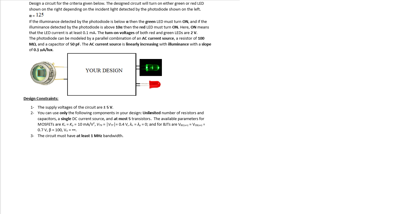
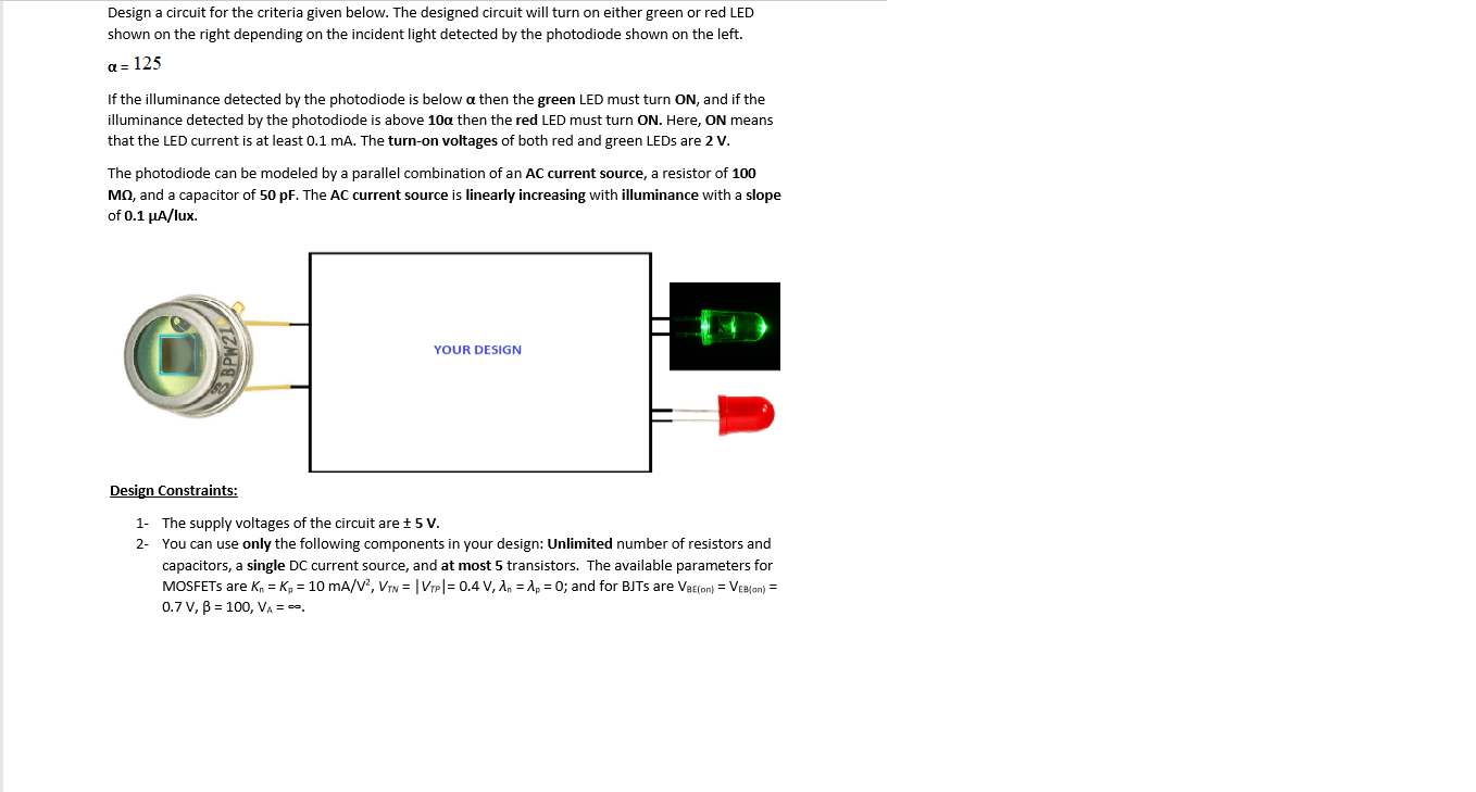
Design a circuit for the criteria given below. The designed circuit will turn on either green or red LED shown on the right depending on the incident light detected by the photodiode shown on the left. a=125 If the illuminance detected by the photodiode is below a then the green LED must turn ON, and if the illuminance detected by the photodiode is above 10a then the red LED must turn ON. Here, ON means that the LED current is at least 0.1 mA. The turn-on voltages of both red and green LEDs are 2 v. The photodiode can be modeled by a parallel combination of an AC current source, a resistor of 100 MO, and a capacitor of 50 pF. The AC current source is linearly increasing with illuminance with a slope of 0.1 UA/lux. YOUR DESIGN Design Constraints: 1- The supply voltages of the circuit are +5V. 2- You can use only the following components in your design: Unlimited number of resistors and capacitors, a single DC current source, and at most 5 transistors. The available parameters for MOSFETs are kn = K = 10 mA/V2, VTN = | VTP = 0.4 V, 1.. = 12 = 0; and for BJTs are VEcon} = Vee/an) = 0.7 V, B = 100, VA = . The circuit must have at least MHz bandwidth. Design a circuit for the criteria given below. The designed circuit will turn on either green or red LED shown on the right depending on the incident light detected by the photodiode shown on the left. a = 125 If the illuminance detected by the photodiode is below a then the green LED must turn ON, and if the illuminance detected by the photodiode is above 10a then the red LED must turn ON. Here, ON means that the LED current is at least 0.1 mA. The turn-on voltages of both red and green LEDs are 2 V. The photodiode can be modeled by a parallel combination of an AC current source, a resistor of 100 MO, and a capacitor of 50 pF. The AC current source is linearly increasing with illuminance with a slope of 0.1 A/lux. BPW21) YOUR DESIGN Design Constraints: 1- The supply voltages of the circuit are +5V. 2- You can use only the following components in your design: Unlimited number of resistors and capacitors, a single DC current source, and at most 5 transistors. The available parameters for MOSFETs are kn = K = 10 mA/V2, Vin = | VTP = 0.4 V, 1.. = 12 = 0; and for BJTs are Ve Econ} = VeBlan) = 0.7V, B = 100, VA = -- Design a circuit for the criteria given below. The designed circuit will turn on either green or red LED shown on the right depending on the incident light detected by the photodiode shown on the left. a=125 If the illuminance detected by the photodiode is below a then the green LED must turn ON, and if the illuminance detected by the photodiode is above 10a then the red LED must turn ON. Here, ON means that the LED current is at least 0.1 mA. The turn-on voltages of both red and green LEDs are 2 v. The photodiode can be modeled by a parallel combination of an AC current source, a resistor of 100 MO, and a capacitor of 50 pF. The AC current source is linearly increasing with illuminance with a slope of 0.1 UA/lux. YOUR DESIGN Design Constraints: 1- The supply voltages of the circuit are +5V. 2- You can use only the following components in your design: Unlimited number of resistors and capacitors, a single DC current source, and at most 5 transistors. The available parameters for MOSFETs are kn = K = 10 mA/V2, VTN = | VTP = 0.4 V, 1.. = 12 = 0; and for BJTs are VEcon} = Vee/an) = 0.7 V, B = 100, VA = . The circuit must have at least MHz bandwidth. Design a circuit for the criteria given below. The designed circuit will turn on either green or red LED shown on the right depending on the incident light detected by the photodiode shown on the left. a = 125 If the illuminance detected by the photodiode is below a then the green LED must turn ON, and if the illuminance detected by the photodiode is above 10a then the red LED must turn ON. Here, ON means that the LED current is at least 0.1 mA. The turn-on voltages of both red and green LEDs are 2 V. The photodiode can be modeled by a parallel combination of an AC current source, a resistor of 100 MO, and a capacitor of 50 pF. The AC current source is linearly increasing with illuminance with a slope of 0.1 A/lux. BPW21) YOUR DESIGN Design Constraints: 1- The supply voltages of the circuit are +5V. 2- You can use only the following components in your design: Unlimited number of resistors and capacitors, a single DC current source, and at most 5 transistors. The available parameters for MOSFETs are kn = K = 10 mA/V2, Vin = | VTP = 0.4 V, 1.. = 12 = 0; and for BJTs are Ve Econ} = VeBlan) = 0.7V, B = 100, VA =