Question: For the system shown overleaf is protected by IDMT relays: (a) Calculate the nominal (i.e. full load) currents at circuit breaker locations. (b) Select


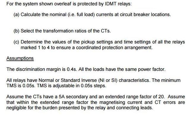
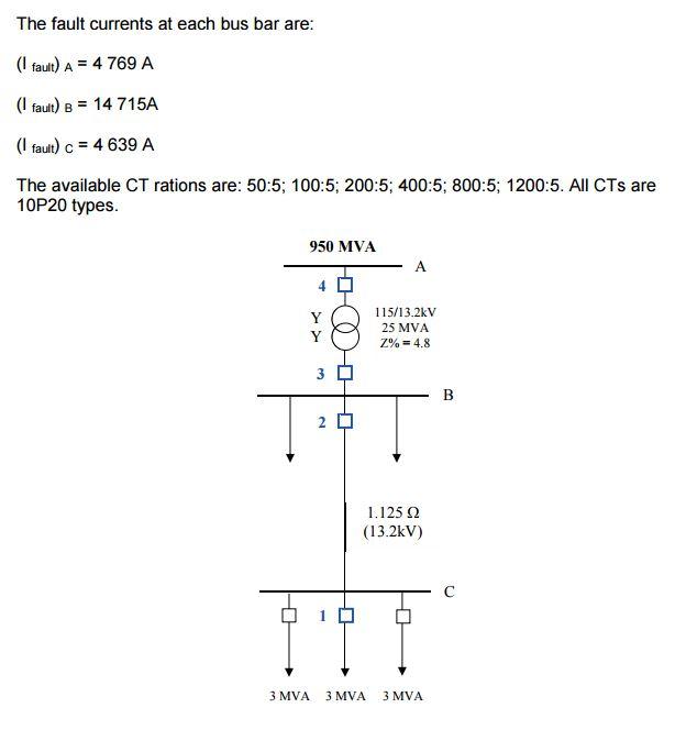
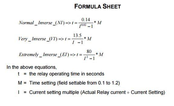
For the system shown overleaf is protected by IDMT relays: (a) Calculate the nominal (i.e. full load) currents at circuit breaker locations. (b) Select the transformation ratios of the CTs. (c) Determine the values of the pickup settings and time settings of all the relays marked 1 to 4 to ensure a coordinated protection arrangement. Assumptions The discrimination margin is 0.4s. All the loads have the same power factor. All relays have Normal or Standard Inverse (NI or SI) characteristics. The minimum TMS is 0.05s. TMS is adjustable in 0.05s steps. Assume the CTs have a 5A secondary and an extended range factor of 20. Assume that within the extended range factor the magnetising current and CT errors are negligible for the burden presented by the relay and connecting leads. The fault currents at each bus bar are: (I fault) A = 4 769 A (I fault) B = 14 715A (I faut) c = 4 639 A The available CT rations are: 50:5; 100:5; 200:5; 400:5; 800:5; 1200:5. All CTs are 10P20 types. 950 MVA 4 0 115/13.2kV Y 25 MVA Y Z% = 4.8 3 0 2 1.125 2 (13.2kV) 3 MVA 3 MVA 3 MVA FORMULA SHEET 0.14 Normal_Inverse_(NI)=> t =- M 10.02 -1 Very Inverse (VI) => t = 13.5 * M I -1 80 * M 1 -1 Extremely Inverse (EI) =>t =- In the above equations, t = the relay operating time in seconds M = Time setting (field settable from 0.1 to 1.2) | = Current setting multiple (Actual Relay current + Current Setting)
Step by Step Solution
3.47 Rating (150 Votes )
There are 3 Steps involved in it
1 1... View full answer

Get step-by-step solutions from verified subject matter experts


