Answered step by step
Verified Expert Solution
Question
1 Approved Answer
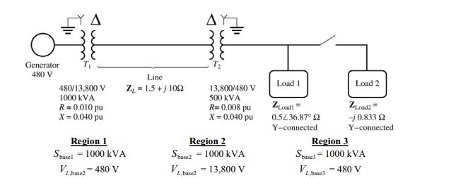
Figure P3-4 shows a power system consisting of a three-phase 480-V 60-Hz generator supplying two loads through a transmission line with a pair of


Figure P3-4 shows a power system consisting of a three-phase 480-V 60-Hz generator supplying two loads through a transmission line with a pair of transformers at either end. (a) Sketch the per-phase equivalent circuit of this power system. (b) With the switch opened, find the real power P, reactive power Q, and apparent power S supplied by the generator. What is the power factor of the generator? (c) With the switch closed, find the real power P, reactive power Q, and apparent power S supplied by the generator. What is the power factor of the generator? (d) What are the transmission losses (transformer plus transmission line losses) in this system with the switch open? With the switch closed? What is the effect of adding Load 2 to the system? off Generator 480 V 480/13,800 V 1000 KVA R = 0.010 pu X = 0.040 pu Line Z = 1.5+j100 Region 1 Shasel = 1000 KVA VL.basc2=480 V 13,800/480 V 500 KVA R=0.008 pu X = 0.040 pu Region 2 Shase21000 KVA VL.base2 = 13,800 V Load 1 ZLoad!= 0.5/36.87 2 Y-connected Load 2 ZLoad2= -j0.833 2 Y-connected Region 3 Shase3= 1000 KVA VL.base3 = 480 V
Step by Step Solution
★★★★★
3.35 Rating (155 Votes )
There are 3 Steps involved in it
Step: 1
The detailed ...
Get Instant Access to Expert-Tailored Solutions
See step-by-step solutions with expert insights and AI powered tools for academic success
Step: 2

Step: 3

Ace Your Homework with AI
Get the answers you need in no time with our AI-driven, step-by-step assistance
Get Started


