

Question: For the circuit shown in Fig. 1, one can have different combinations for the MOSFET T and diode D, as given in Table 1. Assuming
For the circuit shown in Fig. 1, one can have different combinations for the MOSFET T and diode D, as given in Table 1. Assuming that the load current is il = 38 A constant, the components should be selected in such a way that the reverse recovery current peak (IRRM) of the diode (D;) does not cause the transistor (T) current to surpass its rated value (70 A). For this purpose:
(a) Draw the MOSFET current (it) waveforms for its OFF to ON transition (in one cycle of operation) and for different selections of D1, D2, and D3.
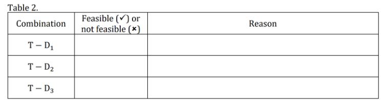
(b) Referring to the obtained diagrams in (a), justify the feasibility or non-feasibility of T - Di combination for all cases in Table 2. Table 1. Code of component Reverse Recovery Rated Current1 Current (A) (A) D1 STTH20003TV 18 180 D2 STTH9012TV 32 150 D3 STTH20004TV1 100 200 TI IRFP4868PbF 16 70 Fig. 1. Table 2. Combination Feasible (v) or not feasible (*) Reason T – D1 T – D2 T – D3 Specifications are given at the temperature of 20°C. 1 RMS current for the diodes, continuous drain current for the MOSFET.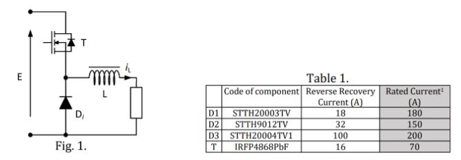
E Table 1. Code of component Reverse Recovery Rated Current Current (A) (A) 180 D1 STTH20003TV STTH9012TV D, 18 D2 32 150 D3 STTH20004TV1 100 200 Fig. 1. IRFP4868PBF 16 70
Step by Step Solution
3.53 Rating (160 Votes )
There are 3 Steps involved in it

Get step-by-step solutions from verified subject matter experts