Answered step by step
Verified Expert Solution
Question
1 Approved Answer
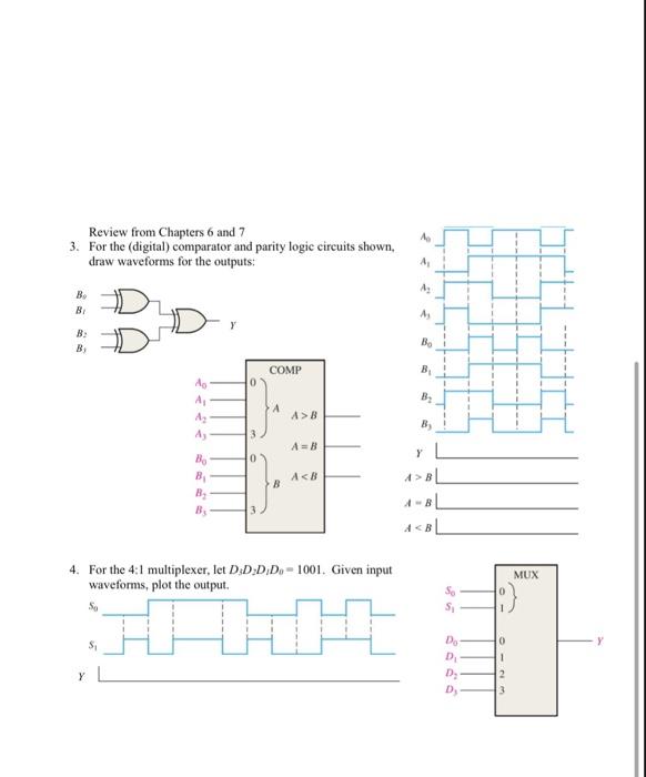
Review from Chapters 6 and 7 3. For the (digital) comparator and parity logic circuits shown, draw waveforms for the outputs: B Bi B

Review from Chapters 6 and 7 3. For the (digital) comparator and parity logic circuits shown, draw waveforms for the outputs: B Bi B By Y So Ao S A A Ay Bo B 0 3 COMP A B A>B 4. For the 4:1 multiplexer, let D.D.DiDo-1001. Given input waveforms, plot the output. HI 14 A=B A BL A
Step by Step Solution
★★★★★
3.55 Rating (162 Votes )
There are 3 Steps involved in it
Step: 1
SONA ROOPA Page No Date Let A B C be the inputs ...
Get Instant Access to Expert-Tailored Solutions
See step-by-step solutions with expert insights and AI powered tools for academic success
Step: 2

Step: 3

Ace Your Homework with AI
Get the answers you need in no time with our AI-driven, step-by-step assistance
Get Started


