

Question
For the Network given in figure , create VLANs according to the figure in Cisco packet tracer and paste your screenshots from Cisco packet tracer.
For the Network given in figure , create VLANs according to the figure in Cisco packet tracer and paste your screenshots from Cisco packet tracer.
Design and simulation of the Communications Network, using Cisco Packet Tracer.
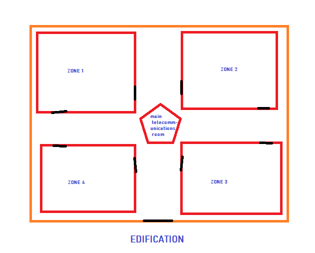
A) Partitioning-Create the topology in the following VLANs (zones 1 to 4, include security cameras for video surveillance in each zone as necessary) the main telecommunications room is in the middle.
B) Link the LAN network to a WAN provided by an ISP, the ISP has access to a Services Cloud.
C) Attach screenshots of the Cisco Packet Tracer step by step.
ZONE 1 ZONE 2 main telecomm unications room ZONE 4 ZONE 3 EDIFICATIONStep by Step Solution
There are 3 Steps involved in it
Step: 1

Get Instant Access to Expert-Tailored Solutions
See step-by-step solutions with expert insights and AI powered tools for academic success
Step: 2

Step: 3
Ace Your Homework with AI
Get the answers you need in no time with our AI-driven, step-by-step assistance
Get Started
Hands-On Database
Authors: Steve Conger
2nd Edition
0133024415, 978-0133024418