Question
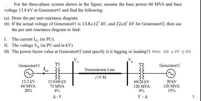
For the three-phase system shown in the figure, assume the base power 60 MVA and base voltage 13.8 kV at Generator#1 and find the

For the three-phase system shown in the figure, assume the base power 60 MVA and base voltage 13.8 kV at Generator#1 and find the following: (a) Draw the per unit reactance diagram. (b) If the actual voltage of Generator#1 is 13.8212 kV, and 2220 kV for Generator#2, then use the per unit reactance diagram to find: I. The current IG (in PU). II. The voltage V (in PU and in kV) III. The power factor value at Generator#2 (and specify is it lagging or leading?) Hint: 0.8 SPF 0.9 Transmission Line NI j10 92 Generator#1 13.2 kV 60 MVA 20% GI T1 13.8/69 kV 75 MVA 8% A: Y T2 69/20 kV 120 MVA 8% Y: A Generator#2 20 kV 120 MVA 15%
Step by Step Solution
3.40 Rating (156 Votes )
There are 3 Steps involved in it
Step: 1

Get Instant Access to Expert-Tailored Solutions
See step-by-step solutions with expert insights and AI powered tools for academic success
Step: 2

Step: 3

Ace Your Homework with AI
Get the answers you need in no time with our AI-driven, step-by-step assistance
Get StartedRecommended Textbook for
Electric Machinery
Authors: Charles Kingsley, Jr, Stephen D. Umans
6th Edition
71230106, 9780073660097, 73660094, 978-0071230100
Students also viewed these Computer Network questions
Question
Answered: 1 week ago
Question
Answered: 1 week ago
Question
Answered: 1 week ago
Question
Answered: 1 week ago
Question
Answered: 1 week ago
Question
Answered: 1 week ago
Question
Answered: 1 week ago
Question
Answered: 1 week ago
Question
Answered: 1 week ago
Question
Answered: 1 week ago
Question
Answered: 1 week ago
Question
Answered: 1 week ago
Question
Answered: 1 week ago
Question
Answered: 1 week ago
Question
Answered: 1 week ago
Question
Answered: 1 week ago
Question
Answered: 1 week ago
Question
Answered: 1 week ago
Question
Answered: 1 week ago
Question
Answered: 1 week ago
Question
Answered: 1 week ago
Question
Answered: 1 week ago
View Answer in SolutionInn App


