

Question
From the slide: implement the following division algorithm: C = 0 ; do { A = A B ; C = C + 1 ;
From the slide:
implement the following division algorithm:
C = 0 ;
do {
A = A B ;
C = C + 1 ;
} while (A >= 0) ;
C = C 1 ;
NOTE: this algorithm uses a do-while loop. It is slightly different than a normal while loop. The computer will always go through the loop once, and then check the condition before it performs it again. This differs from a while loop that will only perform the loop IF the condition is first met.
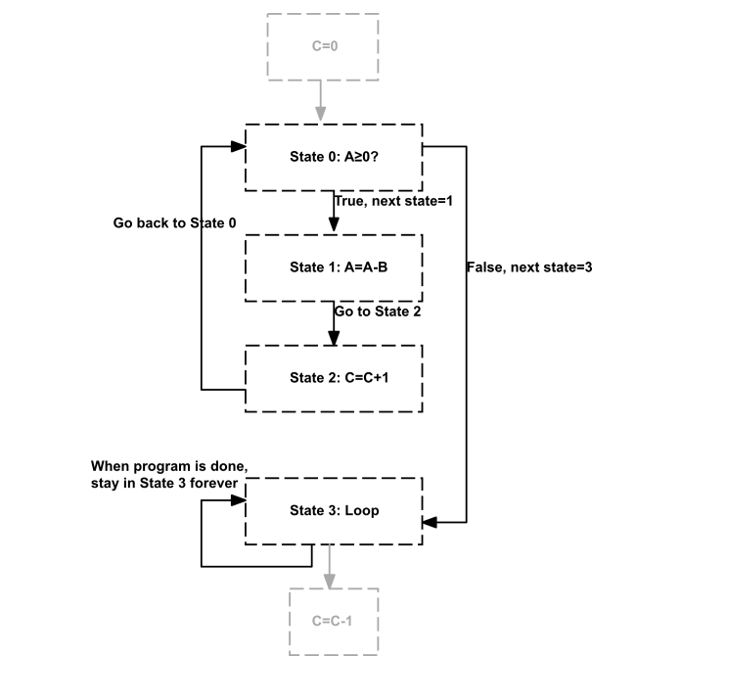
a) Show a Flow Chart, like the one shown in the previous segment, Programming a CPU with Machine Language - The Setup, this will help you break the program into its various states. In a flow chart, operation states (A=B+C) are in boxes while conditional states (while(A
I think I have finished this part:
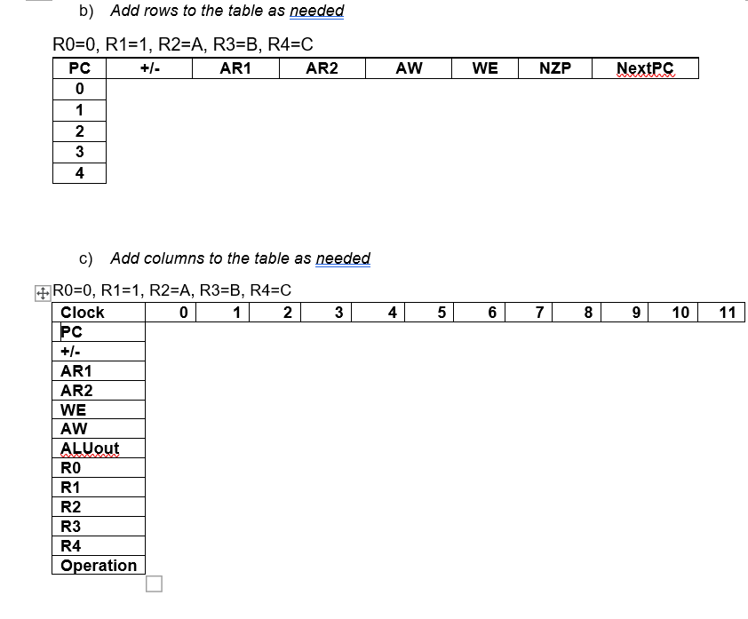
b) Show a table like the one shown on the slide titled Multiply Algorithm: Control Memory Contents from the lecture segment Programming a CPU with Machine Language - The Execution, listing the values of the control signals necessary to implement the algorithm above. The values in your table should be in binary except for registers (use R2 instead of 010), and use the following register allocation: R0=0, R1=1, R2=A, R3=B, R4=C
c) Show an Execution Trace (like the one shown in the same lecture segment, including the control signals) for your program in step (b). Your table should be in decimal. For your trace, assume A=5 and B=2.
The part b) and part c) ask you to fill in the following tables:
Step by Step Solution
There are 3 Steps involved in it
Step: 1

Get Instant Access to Expert-Tailored Solutions
See step-by-step solutions with expert insights and AI powered tools for academic success
Step: 2

Step: 3
Ace Your Homework with AI
Get the answers you need in no time with our AI-driven, step-by-step assistance
Get Started
Relational Database Technology
Authors: Suad Alagic
1st Edition
354096276X, 978-3540962762