Answered step by step
Verified Expert Solution
Question
1 Approved Answer
GI G2 CBA YO YI Y2 Y3 Y4 Y5 Y6 Y7 H X X XHHHHHHHH L X | H L LL LL HHHHHHH H L
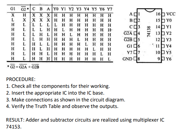
GI G2 CBA YO YI Y2 Y3 Y4 Y5 Y6 Y7 H X X XHHHHHHHH L X | H L LL LL HHHHHHH H L LL HH L H H H H H H H L LH LHHL H L L H H H H H L H L H LLH H H H L H HH H L H L H H H H H H L H H H L LH H H H H HL H L H H H|H H H H H H H I G2 - G2A + G2B Agi B2 G2A 4 G2B 5 Gig6 Y797 16VCC 15YO 14 YI 13Y2 125Y3 1144 1085 9Y6 GND 8 PROCEDURE: 1. Check all the components for their working. 2. Insert the appropriate IC into the IC base. 3. Make connections as shown in the circuit diagram. 4. Verify the Truth Table and observe the outputs. RESULT: Adder and subtractor circuits are realized using multiplexer IC 74153
Step by Step Solution
There are 3 Steps involved in it
Step: 1
Get Instant Access to Expert-Tailored Solutions
See step-by-step solutions with expert insights and AI powered tools for academic success
Step: 2
Step: 3
Ace Your Homework with AI
Get the answers you need in no time with our AI-driven, step-by-step assistance
Get Started