

Question
Giving answer not related to this will result in instanly downvoting! Please test the application and see if its working as desired. Also dont copy
Giving answer not related to this will result in instanly downvoting! Please test the application and see if its working as desired. Also dont copy paste from another, others do not work properly!!
This is the current code and schematics done in Proteus 8 Ardunio Uno Firmware Project.
/* Main.ino file generated by New Project wizard * * Created: Mon Dec 19 2022 * Processor: Arduino Uno * Compiler: Arduino AVR (Proteus) */
// Peripheral Configuration Code (do not edit) //---CONFIG_BEGIN--- #pragma GCC push_options #pragma GCC optimize ("Os")
#include
#pragma GCC pop_options
// Peripheral Constructors CPU &cpu = Cpu; UART &uart = Uart;
void peripheral_setup () { }
void peripheral_loop() { } //---CONFIG_END---
#define HOff LOW #define HOn HIGH #define htr 12 enum Hstates {cooling, heating} htrState=heating+; int ADRes, temp, t0;
void setup () { peripheral_setup(); // TODO: put your setup code here, to run once:
Serial.begin(9600); pinMode(12,OUTPUT); analogReference(INTERNAL); ADRes = analogRead(0); }
void loop() { ADRes = analogRead(0); temp=ADRes*0.10825; // thermostat FSM code if(htrState==cooling){ //HTR if(temp
if(temp>=22) { //HTR htrState=cooling; //HTR digitalWrite(htr,HOff);//HTR Serial.print('-'); } //DBG } }
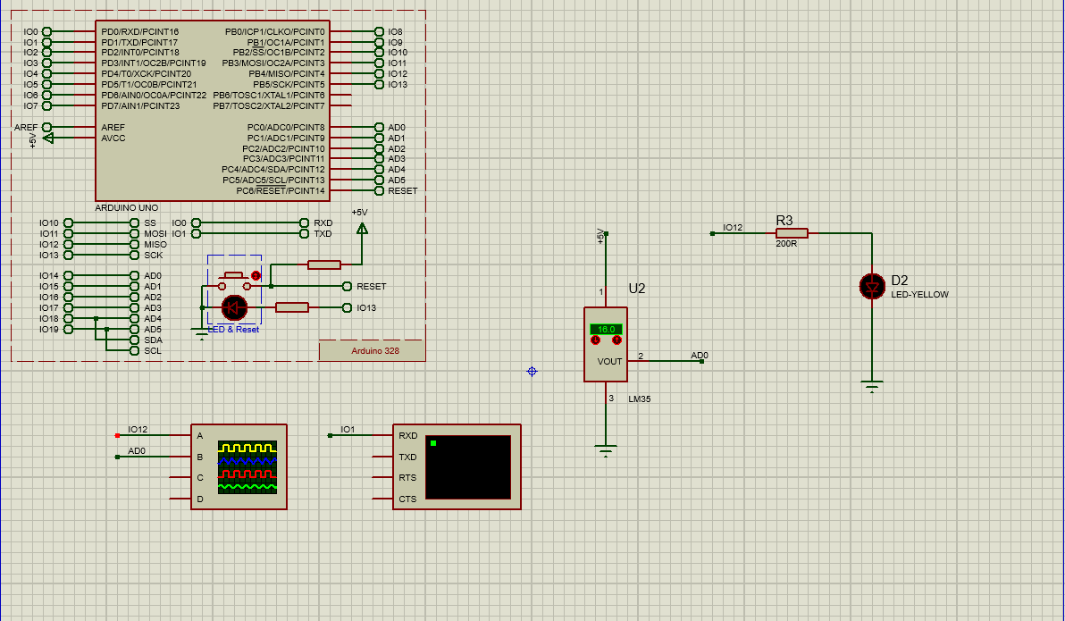
Modify the following code and schematics so that it gives desired outputs mentioned below in the requirements.
A client wanted extra requirements on this thermostat application. He wants the desired temperature Td to be set by a hidden button Sd. Pushing button longer than 5 s shall default Td to 20C, pushing Sd shorter than 2 s shall increment Td by one and flash on internal LED for 1s. Pushing Sd in between 2s to 4s shall decrement Td by one and flash on internal LED for 0.5 s.
1- Prepare the necessary FSM diagram for the described task. Please remember that the time base of the available project was 10ms, and we want to continue with 10 ms period.
2- Assume that you connected a button to pin IO11 with the internal pull-up resistor (i.e., one terminal of the button Sb is grounded to 0V, and the other end is connected to IO11 using a DEFAULT terminal with label IO11). Write the necessary code sections for
i- Additional definition and declaration of variables
ii- Additional setup code for processor and peripherals.
iii- Additional loop code that shall be repeated on runtime.
3- Write a test procedure (i.e. the test code shall be tested by doing this and observing these reactions.)
Step by Step Solution
There are 3 Steps involved in it
Step: 1

Get Instant Access to Expert-Tailored Solutions
See step-by-step solutions with expert insights and AI powered tools for academic success
Step: 2

Step: 3
Ace Your Homework with AI
Get the answers you need in no time with our AI-driven, step-by-step assistance
Get Started
New Trends In Databases And Information Systems Adbis 2019 Short Papers Workshops Bbigap Qauca Sembdm Simpda M2p Madeisd And Doctoral Consortium Bled Slovenia September 8 11 2019 Proceedings
Authors: Tatjana Welzer ,Johann Eder ,Vili Podgorelec ,Robert Wrembel ,Mirjana Ivanovic ,Johann Gamper ,Mikolaj Morzy ,Theodoros Tzouramanis ,Jerome Darmont
1st Edition