Answered step by step
Verified Expert Solution
Link Copied!

Question

1 Approved Answer

HELP with circuit design and verilog!! Please teach me how to design and write the verilog code for this circuit!! i dont understand Introduction There

HELP with circuit design and verilog!!
Please teach me how to design and write the verilog code for this circuit!! i dont understand
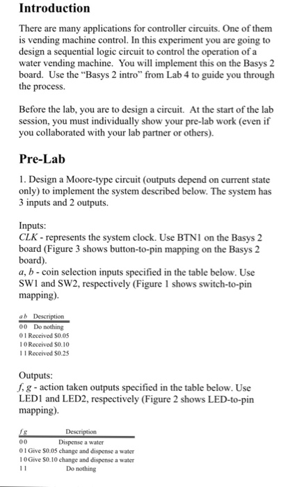
image text in transcribed
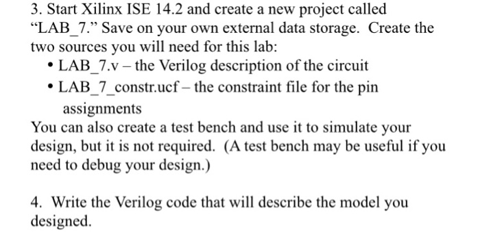
Introduction There are many applications for controller circuits. One of them is vending machine control. In this experiment you are going to design a sequential logic circuit to control the operation of a water vending machine. You will implement this on the Basys 2 board. Use the "Basys 2 intro" from Lab 4 to guide you through the process. Before the lab, you are to design a circui. At the start of the lab session, you must individually show your pre-lab work (even if you collaborated with your lab partner or others) 1. Design a Moore-type circuit (outputs depend on current state only) to implement the system described below. The system has 3 inputs and 2 outputs. Inputs: CLK - represents the system clock. Use BTNI on the Basys 2 board (Figure 3 shows button-to-pin mapping on the Basys 2 board). a, b coin selection inputs specified in the table below. Use SW1 and SW2, respectively (Figure 1 shows switch-to-pin mapping). 00 Do nothing 0 1 Received $0.05 10 Received $0.10 1 1 Received $O.23 Outputs f. g - action taken outputs specified in the table below. Use LEDI and LED2, respectively (Figure 2 shows LED-to-pin mapping) Dispense a water 01 Give S0.0S change and dispense a water 1 0 Give SO.10 change and dispense a water Do nothing Details about the design: 1. The price of a water is $0.15 2. The machine can accept $0.25, $0.10, and $0.05 coins. 3. The machine dispenses a water as soon as it has received $0.15 or more. 4. If the amount received exceeds S0.15, then return the correct change to the customer. 3. Start Xilinx ISE 14.2 and create a new project called "LAB_7." Save on your own external data storage. Create the two sources you will need for this lab: LAB_7.v - the Verilog description of the circuit LAB_7_constr.ucf-the constraint file for the pin assignments You can also create a test bench and use it to simulate your design, but it is not required. (A test bench may be useful if you need to debug your design.) 4. Write the Verilog code that will describe the model you designed

Step by Step Solution

There are 3 Steps involved in it

Step: 1

blur-text-image

Get Instant Access to Expert-Tailored Solutions

See step-by-step solutions with expert insights and AI powered tools for academic success

Step: 2

blur-text-image

Step: 3

blur-text-image

Ace Your Homework with AI

Get the answers you need in no time with our AI-driven, step-by-step assistance

Get Started

Recommended Textbook for

Visualizing Health And Healthcare Data Creating Clear And Compelling Visualizations To See How Youre Doing

Authors: Katherine Rowell ,Lindsay Betzendahl ,Cambria Brown

1st Edition

1119680883, 978-1119680888

More Books

Students also viewed these Databases questions