Hi, I am using Vivado to program my BASYS 3 board, how do I write Verilog code in order to play the below functions?
10 switches as inputs
10 LEDs as outputs, 4 seven-segments display as outputs & 7 LED segments on the display.
Only the correct switches inputs, then the LED segments will light up, how do I use the multiplexer or conditional operator to code these functions.
let's say only the switches 0, 2, 4, 7 is input then the 4 seven-segments display will show as 0 1 0 0 as it is operating in active low, 7 LED segments on the display will display 


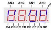
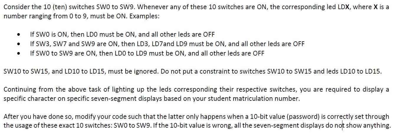
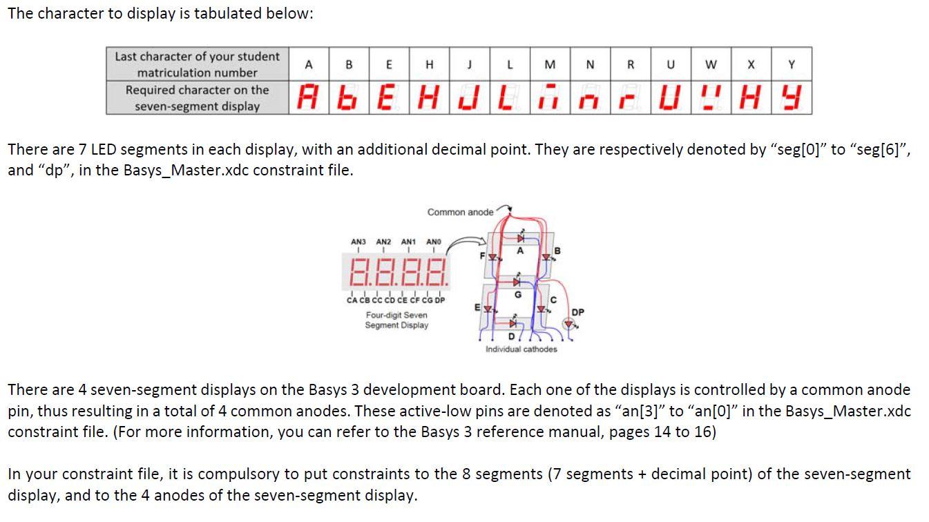
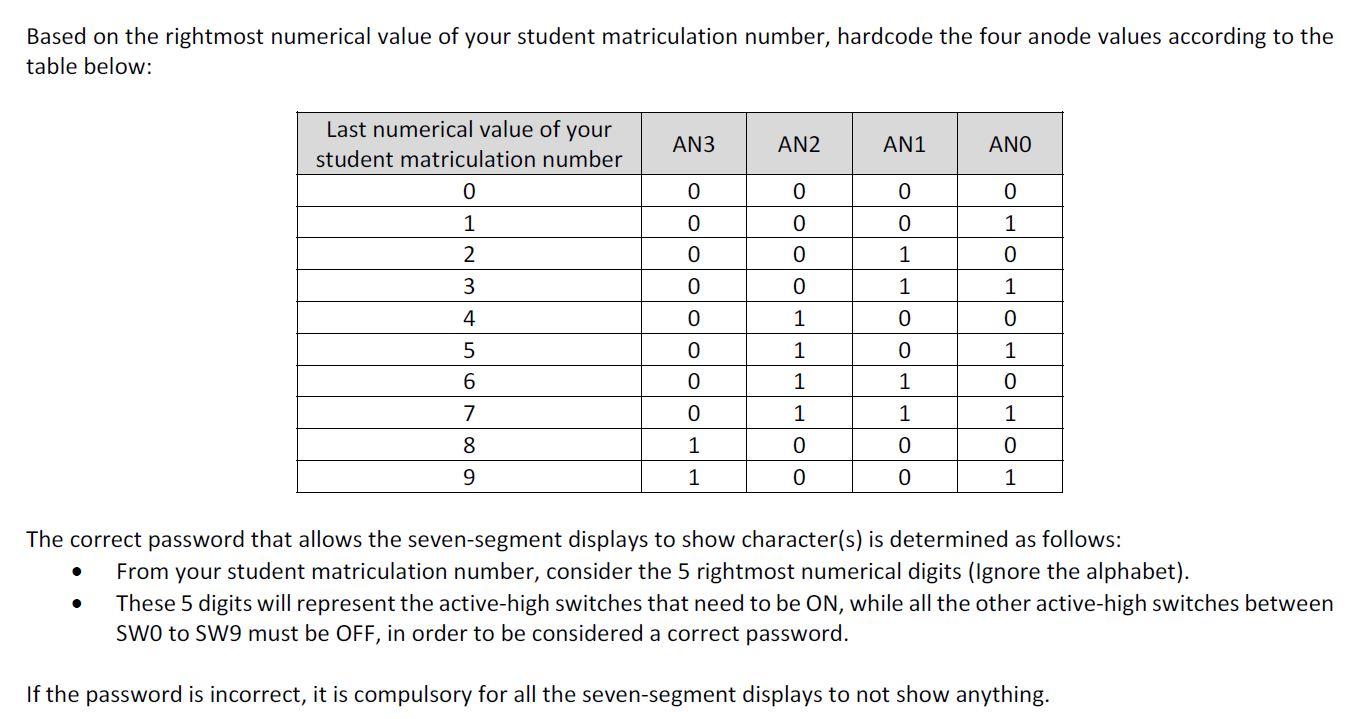
AN3 AN2 AN1 ANO B.8.F.E. IL CA CB CC CD CE CF CG DP Consider the 10 (ten) switches SWO to SW9. Whenever any of these 10 switches are ON, the corresponding led LDX, where X is a number ranging from 0 to 9, must be ON. Examples: . . If SWO is ON, then LDO must be ON, and all other leds are OFF If SW3, SW7 and SW9 are ON, then LD3, LD7and LD9 must be ON, and all other leds are OFF If SWO to SW9 are ON, then LDO to LD9 must be ON, and all other leds are OFF . SW10 to SW15, and LD10 to LD15, must be ignored. Do not put a constraint to switches SW10 to SW15 and leds LD10 to LD15. Continuing from the above task of lighting up the leds corresponding their respective switches, you are required to display a specific character on specific seven-segment displays based on your student matriculation number. After you have done so, modify your code such that the latter only happens when a 10-bit value (password) is correctly set through the usage of these exact 10 switches: SWO to SW9. If the 10-bit value is wrong, all the seven-segment displays do not show anything. The character to display is tabulated below: B E H J L M N R W Y Last character of your student matriculation number Required character on the seven-segment display ALE HULHO U !HY There are 7 LED segments in each display, with an additional decimal point. They are respectively denoted by seg[0] to seg[6), and "dp, in the Basys_Master.xdc constraint file. Common anode AN2 AN1 ANO AN3 1 A B Fy 9.61.61.61. CA CB CC CD CE CE CG OP Four-digit Seven Segment Display Ex DP DK Individual cathodes There are 4 seven-segment displays on the Basys 3 development board. Each one of the displays is controlled by a common anode pin, thus resulting in a total of 4 common anodes. These active-low pins are denoted as "an[3] to an[0]" in the Basys_Master.xdc constraint file. (For more information, you can refer to the Basys 3 reference manual, pages 14 to 16) In your constraint file, it is compulsory to put constraints to the 8 segments (7 segments + decimal point) of the seven-segment display, and to the 4 anodes of the seven-segment display. Based on the rightmost numerical value of your student matriculation number, hardcode the four anode values according to the table below: AN3 AN2 AN1 ANO Last numerical value of your student matriculation number 0 1 2 0 0 0 0 0 1 0 0 1 OOOOOO 0 1 1 3 4 1 0 0 5 1 0 1 0 6 0 1 1 7 0 1 1 1 8 1 0 0 0 0 0 9 1 1 The correct password that allows the seven-segment displays to show character(s) is determined as follows: From your student matriculation number, consider the 5 rightmost numerical digits (Ignore the alphabet). These 5 digits will represent the active-high switches that need to be ON, while all the other active-high switches between SWO to SW9 must be OFF, in order to be considered a correct password. . If the password is incorrect, it is compulsory for all the seven-segment displays to not show anything


