

Question
Hi-tech Net Corp. is operating in three locations in the United States. Their main office is located in New York, NY. They have two branch
Hi-tech Net Corp. is operating in three locations in the United States. Their main office is located in New York, NY. They have two branch offices located in Chicago, IL and Sacramento, CA.
You have just been hired as Hi-tech Net Corp.s consulting engineer to implement their network infrastructure. Both branch offices will be directly connected to the main office in NY via a leased line circuit (point-to-point serial connection).
New Yorks Office IP Information
The main office has four LAN segments: Executive, Engineering, Services, and Native&Management. Each LAN segment is identified by a VLAN number as seen below. For example:
Executive: VLAN 15
Engineering: VLAN 25
Services: VLAN 35
Native&Management: VLAN 99
The organization is using the following network address in NY: 10.150.0.0/16.
Executive: 60 computers only including future growth in this number
Engineering: 80 computers only including future growth in this number
Services: 115 computers including future growth in this number
Native&Management: 12 computers including future growth in this number
*** Future growth means that we already take growth into consideration. Do not try to estimate or add more IP addresses than necessary to avoid getting an incorrect subnet.
Illinois Office IP Information The IL branch has three LAN subnets with 45 IP addresses on each subnet. They use the following network address to obtain the required IL subnets: 10.150.100.0 /24.
Californias Office IP Information The CA branch has three LAN subnets with 25 IP addresses on each subnet. They use the following network address to obtain the required CA subnets: 10.150.200.0 /25.
PHASE I
Tasks to Do.
Task 1: Subnet the 10.150.0.0/16 network for NY and assign the first subnets to Services followed by Engineering. You may need to re-subnet for Executive and Native&Management subnets to avoid wasting IP addresses. Ensure that you re-subnet only the first unused subnet and nothing else. Assign the subnets to Executive and Native&Management.
| New York Office IP | IP Address Range | New Subnet Mask | New Network Address |
| VLAN 15-Executive |
|
|
|
| VLAN 25-Engineering |
|
|
|
| VLAN 35-Services |
|
|
|
| VLAN 99-Native&Management |
|
|
|
Task 2: Subnet the 10.150.100.0 /25 network for IL and assign the last IP address on the three subnets to the Loopback 1, Loopback 2, and Loopback 3 interfaces of the router. We will use a loopback or virtual interface to simulate the LAN subnets. This will speed up configuration and allows us to create our topology without rewiring.
| Illinois Branch IP | IP Address Range | New Subnet Mask | New Network Address |
| Loopback 1 |
|
|
|
| Loopback 2 |
|
|
|
| Loopback 3 |
|
|
|
Task 3: Subnet the 10.150.200.0 /25 network for CA and assign the last IP address on the three subnets to the Loopback 1, Loopback 2, and Loopback 3 interfaces of the router. We will use a loopback or virtual interface to simulate the LAN subnets. This will speed up configuration and allows us to create our topology without rewiring.
| California Branch IP | IP Address Range | New Subnet Mask | New Network Address |
| Loopback 1 |
|
|
|
| Loopback 2 |
|
|
|
| Loopback 3 |
|
|
|
Task 4: Use the following network address (10.1.255.0/25) to find the WAN subnets between NY and IL and NY and CA respectively. Note that there should only be two IP addresses per subnet for each WAN link. Assign the first WAN subnet to NY to IL and the second WAN subnet to NY to CA.
| WAN Subnets | IP Address Range | New Subnet Mask | New Network Address |
| NY to IL |
|
|
|
| NY to CA |
|
|
|
Task 5: Use Microsoft Visio to design the current network topology. Remember to use Loopback interfaces for the subnets in NY, IL, and CA. Use point-to-point interfaces to connect the remote branch offices to NY. See the sample network diagram below. Replace the phrase IP Address by the correct IP address for each interface on the routers. Include the WAN IP addresses on the diagram as well. 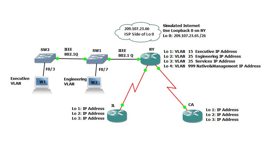
First Major Deliverable in the Project: IP scheme for all three locations (fill in the IP tables above) and the Visio Diagram.
PHASE II
Now that you have completed your first major deliverable in the project, let us move on to the next phase in the project. You need to plan to implement the network. You will configure the switches first.
You should write all required configuration commands with their Command prompt mode in the table, middle column, under the Required Information instructions.
An example:
| Configuration Task | Required Information | Points |
| Router name | RTR1 Router(config)# hostname RTR1 |
Task 1: Configure SW1.
| Configuration Task | Required Information | Points |
| Switch name | SW1
| |
| Secret Password | Netw204
| |
| Disable DNS lookup |
| |
| Username and Password | User= Admin1, Password=cisco123
| |
| Message of the Day (MOTD) Banner | Unauthorized Access is Highly Prohibited!
| |
| VTY | Enable SSH and Disable Telnet.
| |
| Encrypt the clear text passwords | Use the correct command to encrypt clear text passwords.
| |
| Create the required VLANs. | Use the information provided to create the VLANs.
| |
| Assign the management IP address. | Assign the IP Address just before the last valid IP Address on the Native&Management VLAN. VLAN 99 is the Native VLAN.
| |
| Enable the 802.1Q Trunk ports. | Use the correct switchport command to set the Trunk port.
| |
| Configure all other ports as access ports. | Use the interface range command.
| |
| Assign F0/3 to the correct VLAN as per the diagram. | See the network diagram you drew for part 1.
| |
| Shutdown all unused ports. | Disable all unused ports in software.
|
Task 2: Configure SW2.
| Configuration Task | Required Information | Points |
| Switch name | SW2
| |
| Secret Password | Netw204
| |
| Disable DNS lookup |
| |
| Username and Password | User= Admin1, Password=cisco123
| |
| Message of the Day (MOTD) Banner | Unauthorized Access is Highly Prohibited!
| |
| VTY | Enable SSH and Disable Telnet.
| |
| Encrypt the clear text passwords | Use the correct command to encrypt clear text passwords.
| |
| Create the required VLANs. | Use the information provided to create the VLANs.
| |
| Assign the management IP address. | Assign the IP Address just before the last valid IP Address on the Native&Management VLAN. VLAN 99 is the Native VLAN.
| |
| Enable the 802.1Q Trunk ports. | Use the correct switchport command to set the Trunk port.
| |
| Configure all other ports as access ports. | Use the interface range command.
| |
| Assign F0/3 to the correct VLAN as per the diagram. | See the network diagram you drew for part 1.
| |
| Shutdown all unused ports. | Disable all unused ports in software.
|
Task 3: Configure the NY Router.
| Configuration Item or Task | Required Information | Points |
| Configure 802.1Q subinterface .15 on G0/1 | Description Executive LAN Assign VLAN 15. Assign the last valid IP address to this interface.
| |
| Configure 802.1Q subinterface .25 on G0/1 | Description Engineering LAN Assign VLAN 25. Assign the last valid IP address to this interface.
| |
| Configure 802.1Q subinterface .35 on G0/1 | Description Services LAN Assign VLAN 35. Assign the first available address to this interface.
| |
| Configure 802.1Q subinterface .99 on G0/1 | Description Native&Management LAN Assign VLAN 99. Assign the last valid IP address to this interface.
| |
| Activate Interface G0/1 | Bring up interfaces
| |
| OSPF Process ID | 204
| |
| Router ID | 1.1.1.1
| |
| Advertise directly connected networks. | Use classless network addresses Assign all directly connected networks to Area 0
| |
| Set all LAN interfaces as passive. | Type necessary commands to do so.
|
|
| Change the default cost reference bandwidth to support Gigabit interface calculations. | 1000
| |
| Set the serial interface bandwidth. | 768 Kb/s
| |
| Adjust the metric cost of S0/0/0. | Cost: 7500
|
Task 4: Configure the IL Router.
| Configuration Task | Required Information | Points |
| Assign IP addresses to appropriate interfaces including Loopback and serial interfaces. |
|
|
| Activate the nonLoopback interfaces. |
|
|
| OSPF Process ID | 204
|
|
| Router ID | 2.2.2.2
|
|
| Advertise directly connected networks. | Use classless network addresses. Assign interfaces to Area 0. Use a single summary address for the LAN (loopback) interfaces.
|
|
| Set all LAN (Loopback) interfaces as passive. |
|
|
| Change the default cost reference bandwidth to support Gigabit interface calculations. | 1000
|
|
| Set the serial interface bandwidth. | 256 Kb/s
|
|
Note: You will probably notice that all the Loopback IP addresses show up as /32. To change that /32 to the real subnet mask of the Loopback interfaces you need to type the following command on each Loopback interface in the routers.
Interface Loopback 1
ip ospf network point-to-point
Task 5: Configure the CA Router.
| Configuration Task | Required Information | Points |
| Assign IP addresses to appropriate interfaces including Loopback and serial interfaces. |
|
|
| Activate the nonLoopback interfaces. |
|
|
| OSPF Process ID | 204 |
|
| Router ID | 3.3.3.3 |
|
| Advertise directly connected networks. | Use classless network addresses. Assign interfaces to Area 0. Use a single summary address for the LAN (loopback) interfaces. |
|
| Set all LAN (Loopback) interfaces as passive. |
|
|
| Change the default cost reference bandwidth to support Gigabit interface calculations. | 1000 |
|
| Set the serial interface bandwidth. | 256 Kb/s |
|
Task 6: Verify OSPF Configuration
| Question | Points |
| Type the command that displays all connected OSPFv2 routers. Capture the output for your project and explains what you see.
| 1 |
| Type the command that displays the OSPF process ID, router ID, routing networks, address summarization, and passive interfaces configured on a router. Capture the output for your project and explain what you see.
| 1 |
| What command displays only OSPF routes?
| 1 |
| What command displays detail information about the OSPF interfaces, including the authentication method?
| 1 |
| What command displays the OSPF link states types?
| 1 |
| What command displays the OSPF database?
| 1 |
PHASE III
Task 1: Configure the NY router as a DHCPv4 server for the executive and engineering VLAN.
| Configuration Task | Required Information | Points |
| Reserve the first 10 IP addresses in VLAN 15 for static configurations. |
| 1 |
| Reserve the first 10 IP addresses in VLAN 25 for static configurations. |
| 1 |
| Create a DHCP pool for VLAN 15. | Name: EXECUTIVE DNS-Server: 192.168.1.45 Domain-Name: hitech.net Set the default gateway.
| 1 |
| Create a DHCP pool for VLAN 25. | Name: ENGINEERING DNS-Server: 192.168.1.45 Domain-Name: engineering.com Set the default gateway.
| 1 |
Task 2: Restrict Access to the VTY Lines to only come from Native&Management VLAN.
| Configuration Task | Required Information | Points |
| Configure a named access list to only allow Native&Management VLAN to SSH to the routers. | ACL Name: NETMGMT
| 5 |
| Apply the named ACL to the VTY lines. |
| 5 |
| Verify ACL is working as expected. |
| 5 |
Task 3: Configure static and dynamic NAT on NY.
| Configuration Item or Task | Required Information | Points |
| Create a local database with one user account. Use the command username webadmin privilege 15 secret cisco123 | Username: webadmin Password: cisco123 Privilege level: 15
| 5 |
| Enable HTTP server service. | ip http ?
| 2 |
| Configure the HTTP server to use the local database for authentication. | ip http authentication ?
| 2 |
| Create a static NAT to the web server. | Inside Global Address: 209.107.23.66 -->
| 2 |
| Configure NYs Loopback 0 interface with the following IP address. This is a simulated internal web server. | 192.168.1.200/32
| 1 |
| Assign the inside and outside interface for the static NAT. | 192.168.1.200 209.107.23.66 /26
| 1 |
| Configure the dynamic NAT inside private ACL. | Access List: 10 Allow the executive and engineering networks on NY to be translated. Allow a summary of the LANs (loopback) networks on IL and CA to be translated. Do not allow the Services and Native&Management VLANs to be translated.
| 5 |
| Define the pool of usable public IP addresses. | Pool Name: THE_NET Pool of addresses include: 209.107.23.68 209.107.23.75
| 5 |
| Define the dynamic NAT translation. |
| 2 |
Task 4: Secure the network services.
| Configuration Task | Required Information | Points |
| Configure an extended ACL to allow Internet hosts WWW access to the simulated web server on NY by accessing the static NAT address (209.107.23.66 /26) that you configured in Task 3; allow Internet hosts DNS access to the simulated web server on NY by accessing the static NAT address (209.107.23.66 /26) that you configured in Task 3; and prevent traffic from the Internet from pinging internal networks, while continuing to allow LAN interfaces to ping the Internet hosts. | ACL No.: 105
| 10 |
| Apply ACL to the appropriate interface(s). |
| 6 |
Simulated Internet 209.107.23.66 ISP side of L00 Use Loopback 0 on NY Lo 0:209.107.23.65/26 IEEE 802.1Q SW2 SW1 NY IEEE 802.1 Q Lo 1: VLAN 15 Executive IP Address Lo 2: VLAN 25 Engineering IP Address Lo 3: VLAN 35 Services IP Address Lo 4: VLAN 999 Native&Management IP Address FO/3 F0/7 Executive VLAN Engineering VLAN W1 W2 IL CA Lo 1: IP Address Lo 2: IP Address Lo 3: IP Address Lo 1: IP Address Lo 2: IP Address Lo 3: IP Address
Step by Step Solution
There are 3 Steps involved in it
Step: 1

Get Instant Access to Expert-Tailored Solutions
See step-by-step solutions with expert insights and AI powered tools for academic success
Step: 2

Step: 3
Ace Your Homework with AI
Get the answers you need in no time with our AI-driven, step-by-step assistance
Get Started
Sql Data Analytics Made Easy Your Step By Step Guide To Unlocking Datas Hidden Secrets Demystify Complex Concepts And Harness The Power Of Data To Drive Intelligent Decision Making Effortlessly
Authors: L D Knowings
1st Edition
B0CKHWZ35K, 979-8862830880