

Question
Homework Requirement 1. Try to do all the instructions written in the statement. 2. Your actions need to be step by step, and explain your
Homework Requirement
1. Try to do all the instructions written in the statement. 2. Your actions need to be step by step, and explain your actions, even in one sentence. 3.Share the screenshot of the circuit you made in tinkercad. 4. You should definitely show the solution with tinkercad, if your answer is not a circuit set up in tinkercad, don't answer it.
5. After setting up the circuit in tinkercad also show the truth table and kmaps.
---------------------------------------------------------------------------------------------------------------------------
Homework Subject:
Design of a display circuit based on LEDs Using fundamental logic gates (AND, OR, NOT, NAND, NOR and XOR) and LEDS to implement a seven-segment display and its controller on a breadboard.
Given the 4-digit BCD (binary coded decimal) format input, as shown in the figure below, you should be able to view the input bit stream in decimal from 0 to 9 on 20 LEDs. You can simplify the logic circuit as much as possible in this project and you are only allowed to use the components you are provided with.
Figure 1 shows how with 20 LEDs we represent decimal digits. In your project, in order to be able to display decimal digits, you should switch on the proper LEDs.
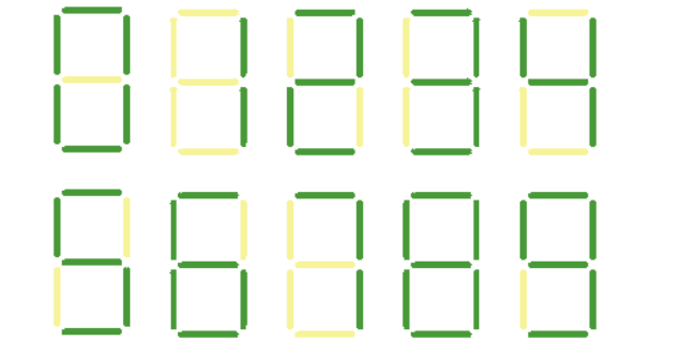
Fig1: Display of decimal digits with 20 LEDs
Tip1: From "0000" to "1001" you will have a 4-digit input and each LED is one of your outputs. First, for a particular binary input sequence, you can decide the LEDs need to be switched on. You need to create a Truth Table to do this and specify the output values for all possible input values. Use dont care conditions in order to simplify your circuit. After that, you need to simplify your circuit by using Karnaugh maps and Boolean algebra after you have completed your Truth Table. Finally, in TinkerCAD, you have to implement the circuit. Tip2: We will consider +5V as "1" and GND as "0" bits to represent binary inputs in this project.
If you don't understand the project, summary; i explain as follows, in the question it is said that our inputs must be binary numbers. Our inputs should be in the form of A B C D, the number of 20 leds means we will have 20 outputs. It also shows that we have 10 different possibilities here, as it will range from 0 to 9. According to these, you can create 20 kmaps, determine the equations, make the connections for each led and proceed.
(I'm writing again, you should definitely show the solution with tinkercad, if your answer is not a circuit set up in tinkercad, don't answer it.)
Step by Step Solution
There are 3 Steps involved in it
Step: 1

Get Instant Access to Expert-Tailored Solutions
See step-by-step solutions with expert insights and AI powered tools for academic success
Step: 2

Step: 3
Ace Your Homework with AI
Get the answers you need in no time with our AI-driven, step-by-step assistance
Get Started
The Temple Of Django Database Performance
Authors: Andrew Brookins
1st Edition
1734303700, 978-1734303704