I need help with writing a lab report on Centripetal Acceleration. Only the introduction, materials method and procedures
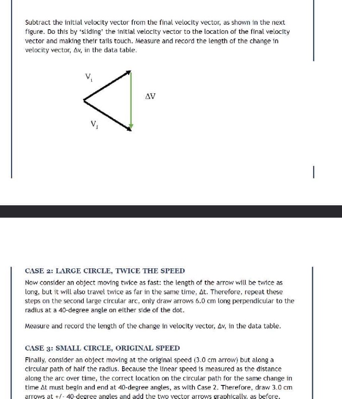
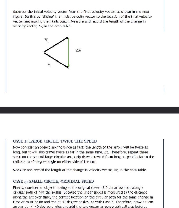
Centripetal Acceleration Introduction Velocity is a vector with both a magnitude and a direction. Since acceleration is a measure of a change in velocity over time, it seems reasonable that either the magnitude of a velocity vector could be changing, or the direction, or both. If magnitude is changing only, then the motion occurs in one dimension and the principles of algebra can be applied to the equations of motion. But suppose the opposite case was true: suppose the direction of the velocity vector was changing but the speed of the object was constant? This activity will use graphical vector analysis to demonstrate that these conditions result in the object moving in a circular path with an acceleration vector pointing toward the center of the circle. Measurement of a paper-and-pencil model of this type of motion will also let us deduce the correct mathematical relationship between the acceleration, speed, and the radius of object moving in a circular path. Required Materials and Equipment . Two copies of the large circular arc . One copy of the small circular are . A protractor and ruler Instructions Download and print out two copies of the large circular arc and one copy of the small circular arc. The center of each arc is identified as a point on the paper. The radius of the larger circle is exactly twice that of the smaller circle: 9.0 cm and 4.5 cm. Measure them to verify this. This activity imagines a point-like object traveling at a constant speed clockwise around the circular path. It can be shown from calculus that the velocity vector for an object moving along a curved arc must always be tangent to the path. It can also be shown from Euclidian geometry that the tangent to a circle is perpendicular to its radius. Graphical analysis will be used to estimate the acceleration of the object at the identified point under different sets of parameters, and the results will be compared to each other. Begin with the larger circular arc. First, mark a point on the arc vertically above the center of the circle. We will analyze the acceleration of an object at this point of its motion. Imagine the initial time starts at a 20-degree angle before the dot and the final time ends at a 20-degree angle after the dot. If we assume the initial time is At/2, then the final time is also At/2, and At = t - ti. Therefore, the acceleration about the point at the top of the circle (halfway between the two identified points) will be a = Av/ At = (vf - vi)/ At The numerical measurement of this change in time is arbitrary because it is assumed to be the same for all trials. CASE 1: LARGE CIRCLE, BASE SPEED Draw the radius from the center of the circular arc to the point, ti, which is 20 degrees before the point of interest. Use a protractor to identify the perpendicular to the radius through that point and draw an arrow 3.0 cm long with its tail at the mark and pointing to the right. Include an arrow head at its tip. Repeat these steps at the mark to the right of the point, as shown in the figure.Subtract the initial velocity vector from the final velocity vector, as shown in the next figure. Do this by 'sliding' the initial velocity vector to the location of the final velocity vector and making their tails touch. Measure and record the length of the change in velocity vector, Av, in the data table. V AV VI CASE 2: LARGE CIRCLE, TWICE THE SPEED Now consider an object moving twice as fast: the length of the arrow will be twice as long, but it will also travel twice as far in the same time, At. Therefore, repeat these steps on the second large circular arc, only draw arrows 6.0 cm long perpendicular to the radius at a 40-degree angle on either side of the dot. Measure and record the length of the change in velocity vector, Av, in the data table. CASE 3: SMALL CIRCLE, ORIGINAL SPEED Finally, consider an object moving at the original speed (3.0 cm arrow) but along a circular path of half the radius. Because the linear speed is measured as the distance along the arc over time, the correct location on the circular path for the same change in time At must begin and end at 40-degree angles, as with Case 2. Therefore, draw 3.0 cm rows at +/- 40-degree angles and add the two vector arrows graphically, as before


