Question: i need to solve this 4 sections using matlab thank you 1 Introduction 1.1 Plant Transfer Function The transfer function of the pitch angle, (),


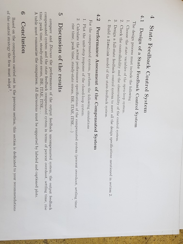
i need to solve this 4 sections using matlab thank you
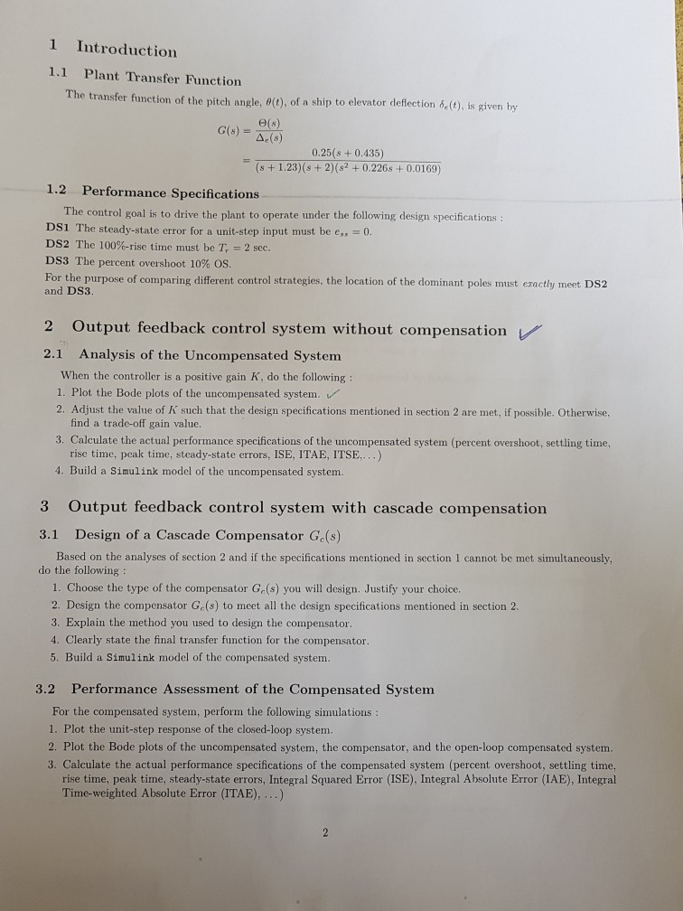
1 Introduction 1.1 Plant Transfer Function The transfer function of the pitch angle, (), of a ship to elevator deflection 6,(), is given by by G(s) (s) ?(s) 0.25(s +0.435) (s + 1.23)(s + 2)(s2 + 0.226s + 0.0169) 1.2 Performance Specifications The control goal is to drive the plant to operate under the following design specifications DSi The steady-state error for a unit-step input must be e,,-0. DS2 The 100%-rise time must be T, = 2 sec. DS3 The percent overshoot 10% OS For the purpose of comparing different control strategies, the location of the dominant poles must eractly meet DS2 and DS3. 2 Output feedback control system without compensation 2.1 Analysis of the Uncompensated System When the controller is a positive gain K, do the following 1, Plot the Bode plots of the uncompensated system. 2. Adjust the value of K such that the design specifications mentioned in section 2 are met, if possible. Otherwise, find a trade-off gain value. 3. Calculate the actual performance specifications of the uncompensated system (percent overshoot, settling time, rise time, peak time, steady-state errors, ISE, ITAE, ITSE,. ..) 4. Build a Simulink model of the uncompensated system 3 Output feedback control system with cascade compensation 3.1 Design of a Cascade Compensator Ge(s) do the following: Based on the analyses of section 2 and if the specifications mentioned in section 1 cannot be met simultaneously, 1. Choose the type of the compensator Ge(s) you will design. Justify your choice. 2. Design the compensator Ge(s) to meet all the design specifications mentioned in section 2. 3. Explain the method you used to design the compensator 4. Clearly state the final transfer function for the compensator. 5. Build a Simulink model of the compensated system. Performance Assessment of the Compensated System For the compensated system, perform the following simulations 1. Plot the unit-step response of the closed-loop system 2. Plot the Bode plots of the uncompensated system, the compensator, and the open-loop compensated system. 3. Calculate the actual performance specifications of the compensated system (percent overshoot, settling time, 3.2 rise time, peak time, steady-state errors, Integral Squared Error (ISE), Integral Absolute Error (IAE), Integral Time-weighted Absolute Error (ITAE),...) 1 Introduction 1.1 Plant Transfer Function The transfer function of the pitch angle, (), of a ship to elevator deflection 6,(), is given by by G(s) (s) ?(s) 0.25(s +0.435) (s + 1.23)(s + 2)(s2 + 0.226s + 0.0169) 1.2 Performance Specifications The control goal is to drive the plant to operate under the following design specifications DSi The steady-state error for a unit-step input must be e,,-0. DS2 The 100%-rise time must be T, = 2 sec. DS3 The percent overshoot 10% OS For the purpose of comparing different control strategies, the location of the dominant poles must eractly meet DS2 and DS3. 2 Output feedback control system without compensation 2.1 Analysis of the Uncompensated System When the controller is a positive gain K, do the following 1, Plot the Bode plots of the uncompensated system. 2. Adjust the value of K such that the design specifications mentioned in section 2 are met, if possible. Otherwise, find a trade-off gain value. 3. Calculate the actual performance specifications of the uncompensated system (percent overshoot, settling time, rise time, peak time, steady-state errors, ISE, ITAE, ITSE,. ..) 4. Build a Simulink model of the uncompensated system 3 Output feedback control system with cascade compensation 3.1 Design of a Cascade Compensator Ge(s) do the following: Based on the analyses of section 2 and if the specifications mentioned in section 1 cannot be met simultaneously, 1. Choose the type of the compensator Ge(s) you will design. Justify your choice. 2. Design the compensator Ge(s) to meet all the design specifications mentioned in section 2. 3. Explain the method you used to design the compensator 4. Clearly state the final transfer function for the compensator. 5. Build a Simulink model of the compensated system. Performance Assessment of the Compensated System For the compensated system, perform the following simulations 1. Plot the unit-step response of the closed-loop system 2. Plot the Bode plots of the uncompensated system, the compensator, and the open-loop compensated system. 3. Calculate the actual performance specifications of the compensated system (percent overshoot, settling time, 3.2 rise time, peak time, steady-state errors, Integral Squared Error (ISE), Integral Absolute Error (IAE), Integral Time-weighted Absolute Error (ITAE),...)
Step by Step Solution
There are 3 Steps involved in it

Get step-by-step solutions from verified subject matter experts


