Answered step by step
Verified Expert Solution
Question
1 Approved Answer
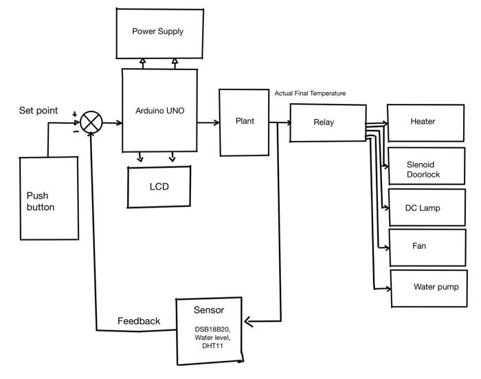
I'm making a block diagram of a Bathroom Water Heater Control system Using a PID Controller. here's the prototype: The prototype design of this bathroom
I'm making a block diagram of a Bathroom Water Heater Control system Using a PID Controller. here's the prototype:
The prototype design of this bathroom water heating system is composed of various components that will form the main function of this system itself. The block diagram of the design of this system is shown in Fig. The input consists of a DS18b20 sensor, a water level sensor, and a DHT11 sensor. The output consists of a heater, doorlock solenoid, DC lamp, fan, water pump, and LCD. This system has two parts, namely automatic door and automatic tank filling. on automatic doors if the user presses the button then the doorlock solenoid is active so that the door can be opened. In addition, pressing the button also activates the room lights, fans and displays the temperature and humidity of the room on the LCD. If the door is closed then the door will automatically be locked. Next is the process of stabilizing the temperature in the bathroom tank. There are three tanks, namely a hot tank, a cold tank, and a main tank. Initially the heater will heat the water in the hot tank up to 45?C. To read the temperature in the tank, this system uses the DS18b20 sensor. When the water has reached that temperature, the PID process runs with a set point between 33-35?C. Before reaching this temperature, the main tank filling will run continuously until the milk reaches the set point. If the main tank is full with a mark on the water level sensor, there is automatically a reduction in the volume of water carried out by the water pump.
Is the block diagram I made correct? if wrong, how about the correct block diagram?

Set point Push button Power Supply Arduino UNO LCD Feedback Sensor DSB18B20, Water level, DHT11 Plant Actual Final Temperature Relay Heater Slenoid Doorlock DC Lamp Fan Water pump
Step by Step Solution
★★★★★
3.40 Rating (150 Votes )
There are 3 Steps involved in it
Step: 1
Solution Any PID controller consist of combination of Proportional Inte...
Get Instant Access to Expert-Tailored Solutions
See step-by-step solutions with expert insights and AI powered tools for academic success
Step: 2

Step: 3

Ace Your Homework with AI
Get the answers you need in no time with our AI-driven, step-by-step assistance
Get Started


