Answered step by step
Verified Expert Solution
Question
1 Approved Answer
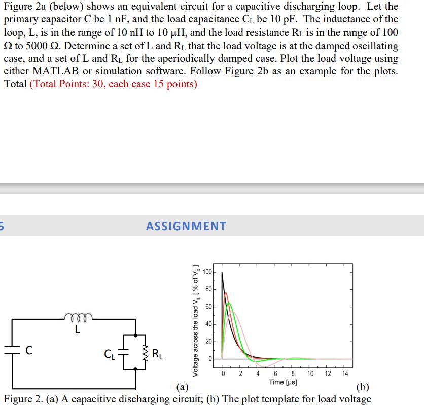
Figure 2a (below) shows an equivalent circuit for a capacitive discharging loop. Let the primary capacitor C be 1 nF, and the load capacitance

Figure 2a (below) shows an equivalent circuit for a capacitive discharging loop. Let the primary capacitor C be 1 nF, and the load capacitance C be 10 pF. The inductance of the loop, L, is in the range of 10 nH to 10 H, and the load resistance RL is in the range of 100 to 5000 N. Determine a set of L and R that the load voltage is at the damped oscillating case, and a set of L and R for the aperiodically damped case. Plot the load voltage using either MATLAB or simulation software. Follow Figure 2b as an example for the plots. Total (Total Points: 30, each case 15 points) 5 C m L CL ASSIGNMENT R Voltage across the load V [% of V] 100 80 60 10 20 0 2 4 6 8 Time [us] 10 12 14 (a) (b) Figure 2. (a) A capacitive discharging circuit; (b) The plot template for load voltage
Step by Step Solution
★★★★★
3.60 Rating (157 Votes )
There are 3 Steps involved in it
Step: 1
The time constant of the circuit denoted by is given by RL R C C where RL is the load resistance and ...
Get Instant Access to Expert-Tailored Solutions
See step-by-step solutions with expert insights and AI powered tools for academic success
Step: 2

Step: 3

Ace Your Homework with AI
Get the answers you need in no time with our AI-driven, step-by-step assistance
Get Started


