

Question: In this project, you will be implementing combinational logic circuits in Logisim to handle button input and (eventually) handle output selection from one of four
In this project, you will be implementing combinational logic circuits in Logisim to handle button input and (eventually) handle output selection from one of four arithmetic circuits (we will talk more about why we need this when we cover chapter 4). The two combinational digital circuits you will implement as subcircuits are discussed in chapter 2: a multiplexor and a priority encoder. You will then use both subcircuits to make a single verification circuit. The following are specifications for each subcircuit.
Multiplexor: For your calculator, you will need a 4x1 multiplexor (mux) with four 8-bit inputs and an 8-bit output. For this project, however, 4-bit inputs and a 4-bit output are sufficient. In other words, using a pair of selector bits your mux should be able to pass through a single 4-bit input as the 4-bit output. To start, you should implementing a 4x1 mux with 1-bit inputs and a 1-bit output in as a subcircuit. A 4x1 mux with 2-bit inputs can be made using a pair of 4x1 muxes with 1-bit inputs where each bit of the output is selected by a different mux. A 4x1 mux with 4-bit inputs can then similarly be made using a pair of 2-bit 4x1 muxes.
Priority Encoder: A priority encoder takes a specific number of input bits and represents the position (meaning the power of two exponent) of the most significant bit that is set (the bit farthest to the left that has a value of 1) in binary. Your priority encoder will have four 1-bit inputs and three 1-bit outputs: two bits used for the representation, in binary, of the position of the highest bit set and a valid bit that is 1 if at least one input bit is set. As one example of a potential input and expected output, suppose all 4 input bits are merged into a single binary representation of 01102. In this case the binary output should be 102 (which is equal to 210) and the valid bit should be 1. This output is generated because the bit in the 22 position is set. Although the 2 1 position bit is also set, it does not affect the output because it is not the most significant set bit. As another example, if the input is 00102 then the output would be 012 (= 110).
Circuit Design Document
There are two deliverables for this project. The first deliverable is a circuit design document, which should be submitted as a single PDF (you may use whatever method you are comfortable with to create the PDF, but I recommend using a word processor such as MS Word or Google Docs. Please ask if you are unsure how to do this). This document should include a truth table for both the multiplexor (the truth table can be for a 4x1 mux with 1-bit inputs) and the priority encoder. These truth tables should then be convert into to Boolean equations. I highly recommend that you simplify these equations before proceeding to implementation in Logisim because this will reduce the difficulty of laying out the circuit. That being said, I am not requiring that you simplify your Boolean equations (and in some cases a less simplified equation is easier to create as a schematic). You should not attempt to implement anything in Logisim until you have completed your design document.
Verification Circuit
The second deliverable is a verification circuit, shown below, to demonstrate that your multiplexor and priority encoder work correctly.
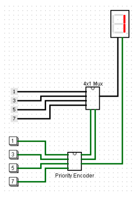
The 4 inputs to the priority encoder are buttons (found in the Logisim Input/Output folder) and the 4 inputs to the mux are constants (found in the Wiring folder), which have been set as 4-bit outputs with the values 1, 3, 5, and 7. Labels can be added to buttons (and other elements) by selecting the item with the editor cursor and modifying the Label attribute. The two outputs that make up the binary representation of the encoder are used as the selectors for the mux. The valid bit of the encoder is connected to the decimal point input of the hex digit display. The 4-bit output of the mux is connected to the 4-bit input of the hex digit display. The purpose of the verification circuit is the show that the encoder correctly encodes a binary value for each of its inputs by using the encoder outputs to select a specific input to the mux and control the decimal point on the hex digit. The seven-segment portion of the hex digit is used to display which of the muxs inputs is currently selected and the decimal point is used to indicate if the valid bit is set. If the any of the buttons are pressed then the decimal point should be turned on. If none of the buttons are pressed then the hex digit should display a 1 with the decimal point off. A demo video of the verification circuit can be found on Blackboard in the Chapter 2 Lecture Videos content folder. NOTE: For your priority encoder and multiplexor subcircuits, please be sure to add labels on all input and output pins. If your verification circuit does not work and your subcircuits do not have pin labels, your submission will be given a zero and you will be asked to resubmit your project with pin labels.
Circuit Reuse in Future Projects: The circuits you are asked to design and implement for this project already exist as circuit elements in the Plexers folder on Logisim. In future projects, you may choose to use either the circuits you implement in this project or the ones included with Logisim. A warning, however, for this project: if any of the premade circuit elements found in the Plexers folder are used in your project you will receive a zero on the circuit portion of the project score.
4x1 Mux Priority Encoder
Step by Step Solution
There are 3 Steps involved in it

Get step-by-step solutions from verified subject matter experts