it can be finished without running the code
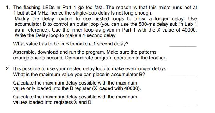
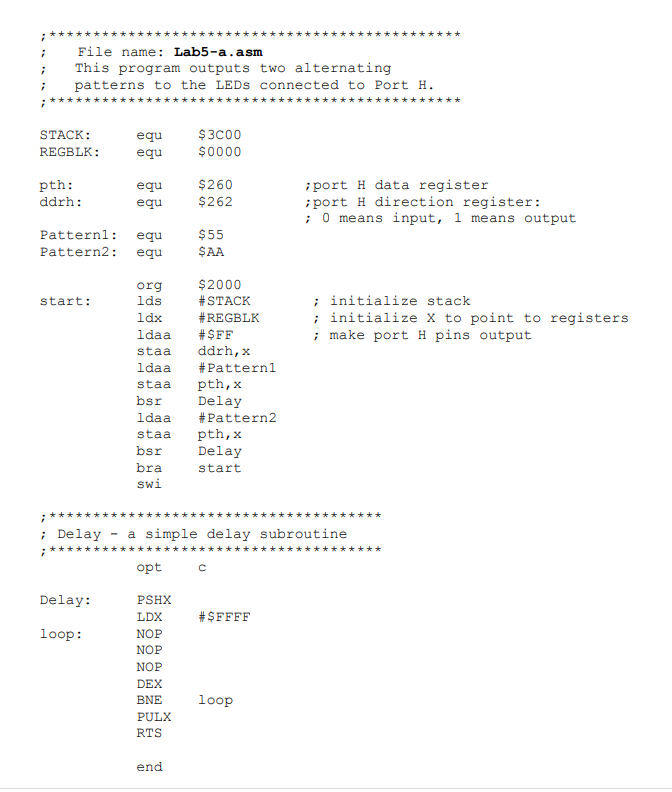
1. The flashing LEDs in Part 1 go too fast. The reason is that this micro runs not at 1 but at 24 MHz; hence the single-loop delay is not long enough. Modify the delay routine to use nested loops to allow a longer delay. Use accumulator B to control an outer loop (you can use the 500-ms delay sub in Lab 1 as a reference). Use the inner loop as given in Part 1 with the X value of 40000. Write the Delay loop to make a 1 second delay. What value has to be in B to make a 1 second delay? Assemble, download and run the program. Make sure the patterns change once a second. Demonstrate program operation to the teacher. 2. It is possible to use your nested delay loop to make even longer delays. What is the maximum value you can place in accumulator B? Calculate the maximum delay possible with the maximum value only loaded into the B register (X loaded with 40000). Calculate the maximum delay possible with the maximum values loaded into registers X and B. i i File name: Lab5-a.asm This program outputs two alternating patterns to the LEDs connected to Port H. i STACK: REGBLK: equ equ $3000 $0000 pth: ddrh: equ equ $260 $262 port H data register ;port H direction register: ; O means input, 1 means output Pattern: Pattern2: equ equ $55 SAA start: ; initialize stack ; initialize X to point to registers ; make port H pins output org lds 1dx ldaa staa ldaa staa bsr ldaa staa bsr bra swi $2000 #STACK #REGBLK #SFF ddrh,x #Patterni pth, x Delay #Pattern2 pth, x Delay start i ; Delay - a simple delay subroutine opt Delay: #SFFFF loop: PSHX LDX NOP NOP NOP DEX BNE PULX RTS loop end 1. The flashing LEDs in Part 1 go too fast. The reason is that this micro runs not at 1 but at 24 MHz; hence the single-loop delay is not long enough. Modify the delay routine to use nested loops to allow a longer delay. Use accumulator B to control an outer loop (you can use the 500-ms delay sub in Lab 1 as a reference). Use the inner loop as given in Part 1 with the X value of 40000. Write the Delay loop to make a 1 second delay. What value has to be in B to make a 1 second delay? Assemble, download and run the program. Make sure the patterns change once a second. Demonstrate program operation to the teacher. 2. It is possible to use your nested delay loop to make even longer delays. What is the maximum value you can place in accumulator B? Calculate the maximum delay possible with the maximum value only loaded into the B register (X loaded with 40000). Calculate the maximum delay possible with the maximum values loaded into registers X and B. i i File name: Lab5-a.asm This program outputs two alternating patterns to the LEDs connected to Port H. i STACK: REGBLK: equ equ $3000 $0000 pth: ddrh: equ equ $260 $262 port H data register ;port H direction register: ; O means input, 1 means output Pattern: Pattern2: equ equ $55 SAA start: ; initialize stack ; initialize X to point to registers ; make port H pins output org lds 1dx ldaa staa ldaa staa bsr ldaa staa bsr bra swi $2000 #STACK #REGBLK #SFF ddrh,x #Patterni pth, x Delay #Pattern2 pth, x Delay start i ; Delay - a simple delay subroutine opt Delay: #SFFFF loop: PSHX LDX NOP NOP NOP DEX BNE PULX RTS loop end