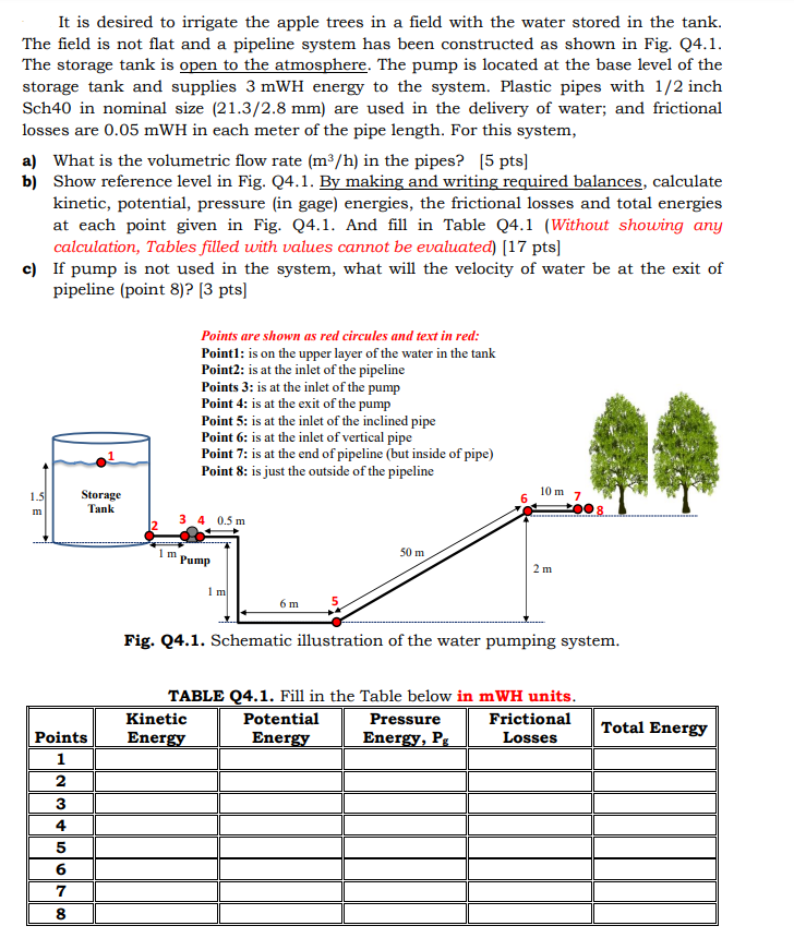
It is desired to irrigate the apple trees in a field with the water stored in the tank. The field is not flat and a pipeline system has been constructed as shown in Fig. Q4.1. The storage tank is open to the atmosphere. The pump is located at the base level of the storage tank and supplies 3mWH energy to the system. Plastic pipes with 1/2 inch Sch40 in nominal size (21.3/2.8mm) are used in the delivery of water; and frictional losses are 0.05mWH in each meter of the pipe length. For this system, a) What is the volumetric flow rate (m3/h) in the pipes? [5 pts] b) Show reference level in Fig. Q4.1. By making and writing required balances, calculate kinetic, potential, pressure (in gage) energies, the frictional losses and total energies at each point given in Fig. Q4.1. And fill in Table Q4.1 (Without showing any calculation, Tables filled with values cannot be evaluated) [17 pts] c) If pump is not used in the system, what will the velocity of water be at the exit of pipeline (point 8)? [3 pts] Fig. Q4.1. Schematic illustration of the water pumping system. TABLE Q4.1. Fill in the Table below in mWH units. It is desired to irrigate the apple trees in a field with the water stored in the tank. The field is not flat and a pipeline system has been constructed as shown in Fig. Q4.1. The storage tank is open to the atmosphere. The pump is located at the base level of the storage tank and supplies 3mWH energy to the system. Plastic pipes with 1/2 inch Sch40 in nominal size (21.3/2.8mm) are used in the delivery of water; and frictional losses are 0.05mWH in each meter of the pipe length. For this system, a) What is the volumetric flow rate (m3/h) in the pipes? [5 pts] b) Show reference level in Fig. Q4.1. By making and writing required balances, calculate kinetic, potential, pressure (in gage) energies, the frictional losses and total energies at each point given in Fig. Q4.1. And fill in Table Q4.1 (Without showing any calculation, Tables filled with values cannot be evaluated) [17 pts] c) If pump is not used in the system, what will the velocity of water be at the exit of pipeline (point 8)? [3 pts] Fig. Q4.1. Schematic illustration of the water pumping system. TABLE Q4.1. Fill in the Table below in mWH units


