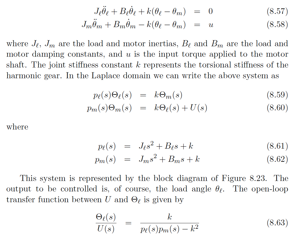
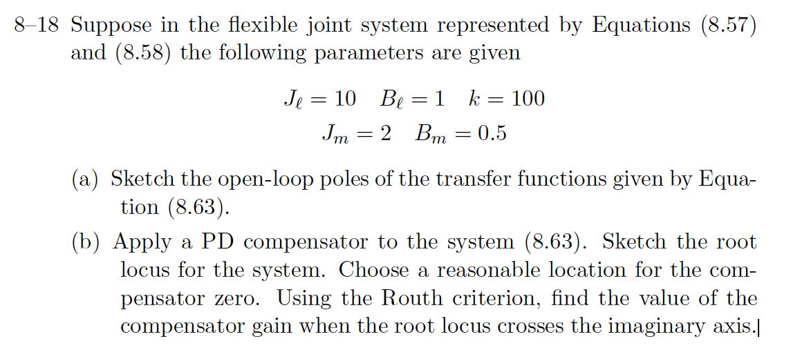
Question: Jee + Bee+k(0e 0m) - Jm0m + Bmm k(Oe Om) - == 0 = u (8.57) (8.58) where Je, Jm are the load and


Jee + Bee+k(0e 0m) - Jm0m + Bmm k(Oe Om) - == 0 = u (8.57) (8.58) where Je, Jm are the load and motor inertias, Be and Bm are the load and motor damping constants, and u is the input torque applied to the motor shaft. The joint stiffness constant k represents the torsional stiffness of the harmonic gear. In the Laplace domain we can write the above system as Pe(s)e(s) Pm(s)em(s) = kem(s) ke(s) + U(s) = (8.59) (8.60) where Pe(s) = Jes + Bes+k Pm(s) = Jms + Bms + k (8.61) (8.62) This system is represented by the block diagram of Figure 8.23. The output to be controlled is, of course, the load angle . The open-loop transfer function between U and O is given by Oe(s) k U(s) Pe(s)Pm(s) - k2 (8.63) 8-18 Suppose in the flexible joint system represented by Equations (8.57) and (8.58) the following parameters are given 10 Be = 1 k = 100 Je = Jm = 2 Bm = 0.5 (a) Sketch the open-loop poles of the transfer functions given by Equa- tion (8.63). (b) Apply a PD compensator to the system (8.63). Sketch the root locus for the system. Choose a reasonable location for the com- pensator zero. Using the Routh criterion, find the value of the compensator gain when the root locus crosses the imaginary axis.|
Step by Step Solution
There are 3 Steps involved in it

Get step-by-step solutions from verified subject matter experts


