Question: Lab A - RC Circuits You may work in your regular lab groups (4 or fewer people), but make sure to turn in your own


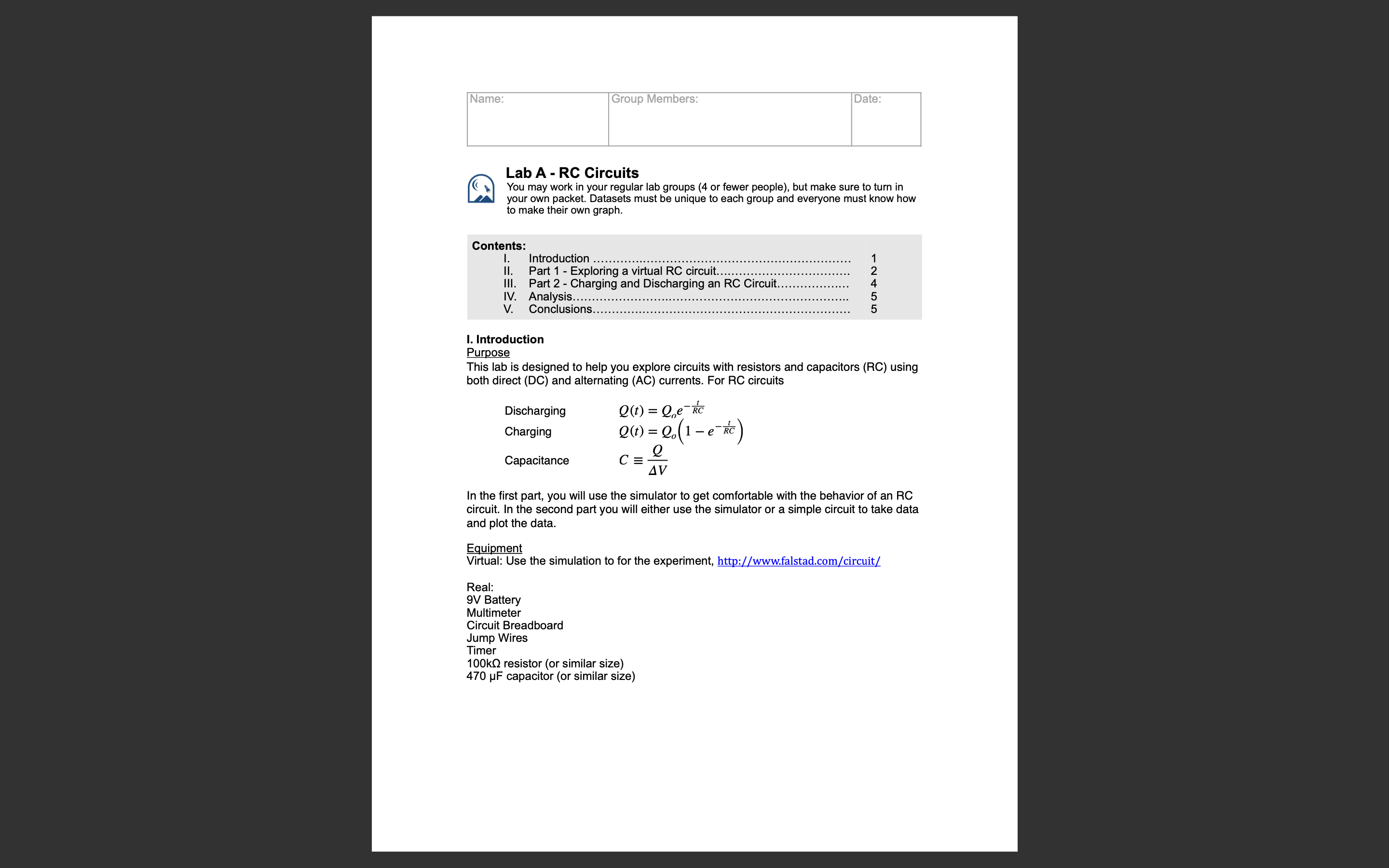
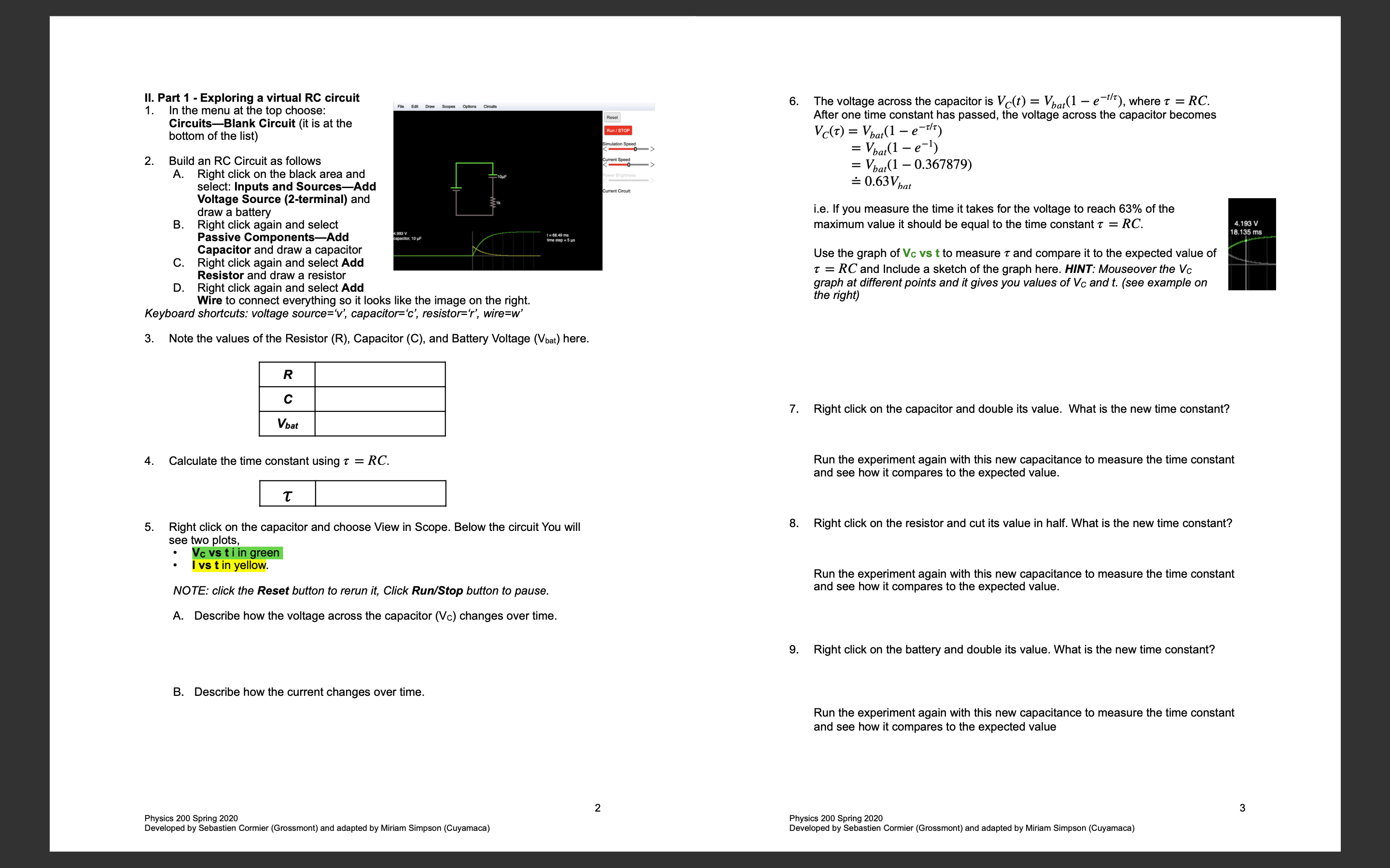
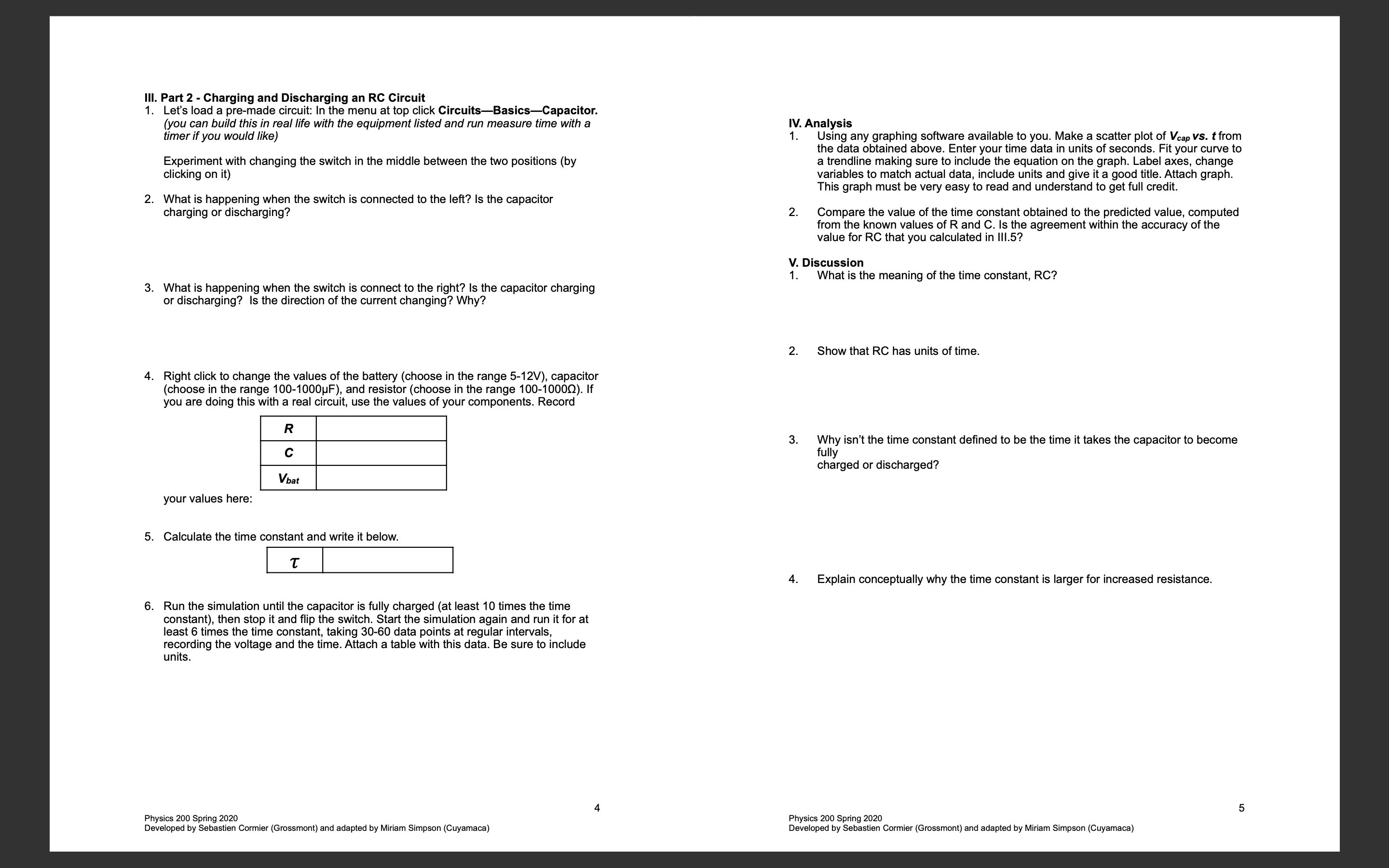
Lab A - RC Circuits You may work in your regular lab groups (4 or fewer people), but make sure to turn in your own packet. Datasets must be unique to each group and everyone must know how to make their own graph. Contents: I Introduction Il. Part 1 - Exploring a virtual circui Ill. Part 2 - Charging and Discharging an RC Circuit. IV. Analysis. V. Conclusions. I. Introduction Purpose This lab is designed to help you explore circuits with resistors and capacitors (RC) using both direct (DC) and alternating (AC) currents. For RC circuits Discharging o = Q,,e' Charging oW = Qo(l - e') Capacitance C= g AV In the first part, you will use the simulator to get comfortable with the behavior of an RC circuit. In the second part you will either use the simulator or a simple circuit to take data and plot the data. Equipment Virtual: Use the simulation to for the experiment, http://www.falstad.com/circuit/ Real: 9V Battery Multimeter Circuit Breadboard Jump Wires Timer 100kQ resistor (or similar size) 470 pF capacitor (or similar size) 1. P 1. art 1 - Exploring a virtual RC circuit In the menu at the top choose: CircuitsBlank Circuit (it is at the bottom of the list) Build an RC Circuit as follows A. Right click on the black area and select: Inputs and SourcesAdd Voltage Source (2-terminal) and draw a battery Right click again and select Passive ComponentsAdd Capacitor and draw a capacitor Right click again and select Add Resistor and draw a resistor D. Right click again and select Add Wire to connect everything so it looks like the image on the right. Keyboard shortcuts: voltage source="v', capacitor="c', resistor="", wire=w'" 8 Note the values of the Resistor (R), Capacitor (C), and Battery Voltage (Vbat) here. R c Vbat Calculate the time constant using 7 = RC. L T | Right click on the capacitor and choose View in Scope. Below the circuit You will see two plots, * Vcvstiingreen lvstinyellow. NOTE: click the Reset button to rerun it, Click Run/Stop button to pause. A. Describe how the voltage across the capacitor (Vc) changes over time. B. Describe how the current changes over time. The voltage across the capacitor is V(t) = V(1 e~7), where 7 = RC. After one time constant has passed, the voltage across the capacitor becomes Ve(@ = V(1 = 7 = Vol =) = Vpu(1 = 0.367879) =0.63V,,, i.e. If you measure the time it takes for the voltage to reach 63% of the maximum value it should be equal to the time constant 7 = RC. Use the graph of Vc vs t to measure 7 and compare it to the expected value of 7 = RC and Include a sketch of the graph here. HINT: Mouseover the V graph at different points and it gives you values of V and t. (see example on the right) Right click on the capacitor and double its value. What is the new time constant? Run the experiment again with this new capacitance to measure the time constant and see how it compares to the expected value. Right click on the resistor and cut its value in half. What is the new time constant? Run the experiment again with this new capacitance to measure the time constant and see how it compares to the expected value. Right click on the battery and double its value. What is the new time constant? Run the experiment again with this new capacitance to measure the time constant and see how it compares to the expected value Physics 200 Spring 2020 Physics 200 Spring 2020 Developed by Sebastien Cormier (Grossmont) and adapted by Miriam Simpson (Cuyamaca) Developed by Sebastien Cormier (Grossmont) and adapted by Miriam Simpson (Cuyamaca) . Part 2 - Charging and Discharging an RC Circuit Let's load a pre-made circuit: In the menu at top click CircuitsBasicsCapacitor. (you can build this in real life with the equipment listed and run measure time with a timer if you would like) Experiment with changing the switch in the middle between the two positions (by clicking on it) . What is happening when the switch is connected to the left? Is the capacitor charging or discharging? . What is happening when the switch is connect to the right? Is the capacitor charging or discharging? s the direction of the current changing? Why? Right click to change the values of the battery (choose in the range 5-12V), capacitor (choose in the range 100-1000pF), and resistor (choose in the range 100-1000Q). If you are doing this with a real circuit, use the values of your components. Record R c your values here: . Calculate the time constant and write it below. T Run the simulation until the capacitor is fully charged (at least 10 times the time constant), then stop it and flip the switch. Start the simulation again and run it for at least 6 times the time constant, taking 30-60 data points at regular intervals, recording the voltage and the time. Attach a table with this data. Be sure to include units. Physics 200 Spring 2020 Developed by Sebastien Cormier (Grossmont) and adapted by Miriam Simpson (Cuyamaca) IV. Analysis 1. Using any graphing software available to you. Make a scatter plot of Veap vs. t from the data obtained above. Enter your time data in units of seconds. Fit your curve to a trendline making sure to include the equation on the graph. Label axes, change variables to match actual data, include units and give it a good title. Attach graph. This graph must be very easy to read and understand to get full credit. Compare the value of the time constant obtained to the predicted value, computed from the known values of R and C. Is the agreement within the accuracy of the value for RC that you calculated in 111.5? V. Discussion 1. What is the meaning of the time constant, RC? Show that RC has units of time. Why isn't the time constant defined to be the time it takes the capacitor to become fully charged or discharged? Explain conceptually why the time constant is larger for increased resistance. Physics 200 Spring 2020 Developed by Sebastien Cormier (Grossmont) and adapted by Miriam Simpson (Cuyamaca)
Step by Step Solution
There are 3 Steps involved in it

Get step-by-step solutions from verified subject matter experts


