

Question: May you please write a VHDL code for this lab problem. Thanks. 2. 0-15 BCD 7-Segment Controller Design You are to design a circuit that
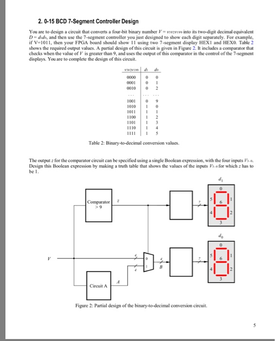
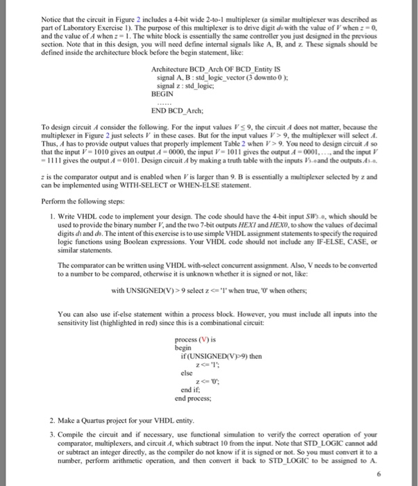
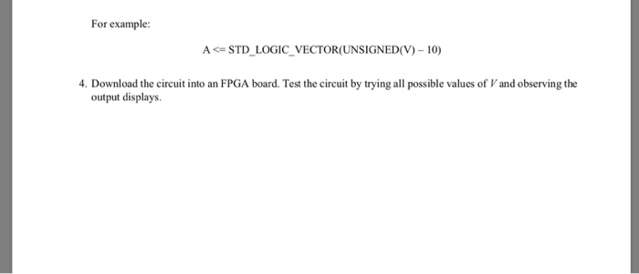
2. 0-15 BCD 7-Segment Controller Design You are to design a circuit that converts a four-bit binary number V- vwe into its two-digit decimal equivalent D = dd, and then use the 7-segment controller you just designed to show each digit separately. For example, if V-1011, then your FPGA board should show 11 using two 7-segment display HEXI and HEXO. Table 2 shows the required output values. A partial design of this circuit is given in Figure 2. It includes a comparator that checks when the value of V is greater than 9, and uses the output of this comparator in the control of the 7-segment displays. You are to complete the design of this circuit. 0001 01 0010 02 1001 09 010 10 1100 2 1101 3 110 4 Table 2: Binary-to-decimal conversion values The outputz for the comparator circuit can be specified using a single Boolean expression, with the four inputs s.o Design this Boolcan expression by making a truth table that shows the values of the inputs V'so for which : has to be 1 Circuit A Figure 2: Partial design of the binary-to-decimal conversion circuit Notice that the circuit in Figure 2 includes a 4-bit wide 2-to-1 multiplexer (a similar multiplexer was described as part of Laboratory Exercise 1). The purpose of this multiplexer is to drive digit do with the value of when-0 and the value of A when 1. The white block is essentially the same controller you just designed in the previous section. Note that in this design, you will need define internal signals like A, B, and z. These signals should boe defined inside the architecture block before the begin statement, like: Architecture BCD Arch OF BCD Entity IS signal A, B:std logic vector (3 downto 0 ) signal z: std logic BEGIN END BCD Arch; To design circuit A consider the following. For the input values Vs9, the circuit A does not matter, because the multiplexer in Figure 2 just selectsV in these cases. But for the input values >9, the multiplexer will select A Thus, A has to provide output values that properly implement Table 2 when V9. You need to design circuit A so that the input V= 1010 gives an output 4-0000, the input V= 1011 gives the output 4-0001,- and the input V -1111 gives the output A -0101. Design circuit A by making a truth table with the inputs 'seand the outputsAs. z is the comparator output and is enabled when Vis larger than 9. B is essentially a multiplexer selected by z and can be implemented using WITH-SELECT or WHEN-ELSE statement Perform the following steps: . Write VHDL code to implement your design. The code should have the 4-bit input SW's, which should be used to provide the binary number V, and the two 7-bit outputs HEXI and HEXo, to show the values of decimal digits di and do. The intent of this exercise is to use simple VHDLassignment statements to specify the required logic functions using Boolean expressions. Your VHDL code should not include any IF-ELSE, CASE, o similar statements. The comparator can be written using VHDL with-select concurrent assignment. Also, V needs to be converted to a number to be compared, otherwise it is unknown whether it is signed or not, like: with UNSIGNED(V)> 9 select zwhen true, when others; You can also use if-else statement within a process block. However, you must include all inputs into the sensitivity list (highlighted in red) since this is a combinational circuit process (V) is if (UNSIGNEDV9) then else end if end process; 2. Make a Quartus project for your VHDL entity. 3. Compile the circuit and if necessary, use functional simulation to verify the correct opcration of your comparator, multiplexers, and circuit A, which subtract 10 from the input. Note that STD LOGIC cannot add or subtract an integer directly, as the compiler do not know if it is signed or not. So you must convert it to a number, perform arithmetic operation, and then convert it back to STD LOGIC to be assigned to A For example: ASTD LOGIC VECTOR(UNSIGNED(V) -10) 4. Download the circuit into an FPGA board. Test the circuit by trying all possible values of V and observing the output displays
Step by Step Solution
There are 3 Steps involved in it

Get step-by-step solutions from verified subject matter experts